Wednesday, April 16, 2014

Posted PCB release v0.1.3

This morning I posted up the v0.1.3 release of the Arduino Alternator Regulator files.  Look through the resource tabs above, I posted:

  • PDF file of the scheamtics
  • .ZIP file with PCB GBR files.
  • .xls with BOM
  • KiCAD  CAD files for Scheamtic and PCB
  • Updated custom  libs, mods, etc files used in support of KiCAD.

This release is what we are going to send off to the fab house to have 10x assembled regulator units completed.  Mostly it was scrubbing and commenting the parts list, but I also:
  • Added self resetting fuses to the NTC ports.
  • Revised Service Port pinout to match 6-pin USB <--> TTL addapter from EBay. (No more modes needed)

I will be sending this package off later today to the FAB house asking for a firm quote, then on to assemble!


Tuesday, April 15, 2014

Burning up Alternators at Idle....

One thing that has always bothered me was when the engine idles down to a lower RPM and the Alternator is still trying to pump out a massive amount of power - regulator will end up driving the field to Full Power 100% field current trying to keep up. The question is: Are Alternators able to handle this? In some ways it is kind of like lugging an engine uphill in high gear..

I know this is not an Alternator Rotor
But you get the idea..

This last week I had someone contact me.  They have been poring over both this Arduino regulator project, as well as its companion http://smartdcgenerator.blogspot.com and asked the question: "Am I doing anything to reduce Field current at low RPMs". He went on to share an experience of a boat using large frame Leece Neville 4900 series alternators (the same 35lb units I use for our main engine house alternator) driving massive loads  to power engine room blowers via inverters. After an extended period of time at idle (and likely in a very hot engine room - these were MTUs in a $$$ go-fast craft), there was a failure in the field - total melt down of the Field / rotor..


My initial intention of adding the 'Small Alt' mode selectable via the DIP switch was to protect smaller framed alternators from prolonged periods of high current output. Ala, that 200A Hot-Rodded alternator in a standard small frame.. Small Alternator mode will cap an alternators output to 75% of its capability (configurable of course), at all charge points. But it seems perhaps more might be needed - especially given the real life experience of someone melting down my beloved Leece Neville large frame alternators just idling around...

So, I have added a new feature to further restrict how hard the field is driven when the engine is at idle.  By sensing this RPMs vis the Stator wire, I can tell when we are near idle - or at least near the lowest RPMs that the engine has been operated at..  And when at idle I now cap the field to 50% of its max drive.  This % is increased up to the max allowed (100% or 75% depending on the DIP switch, and if the defaults have been adjusted).  And there is a new parameter in the $SCA: command to configure this capability.


Blue line shows default idle capping curve.
Red and green give an idea of some other configurable options via the $SCA: command..
Of course you can also use the $SCA: command to also disable this feature. Right now I have the '50%' hard codded in the firmware; starting to get a bit too many configurable parameters. If someone has any feeling for the right % value to use at idle, let me know.  If you want to change it in the firmware look at the  "set_VAWL(float passedV)"  helper function in "calculate_ALT_targets()" 


I hope this will help out some installs.  Though we never had any issue pulling max amps (and max field) for several hours  at a time while idleing around during Christmas Ships with our LN 4900 270A alternator, clearly someone has..   Perhaps I can feel even better now - protecting the Alternator just a bit more...


Thursday, April 10, 2014

Confirming Power Dissipation

As I go through to finalize the next rev of the PCB I though I would revisit my heat calculations.  There are two (three really) sources of heat in the regulator:
  • Darlington pre-voltage regulator (Q1)
  • Final Voltage Regulator (U1)
  • Field FETs (Q2 / Q4)

I calculated the Power Dissipated in Watts for each of these, and here are the results:


For the power supplies I assumed a current draw of 165mA, this is approximately  two times the expected maximum internal current draw. 


FET power dissipated is dominated by static losses (simple "P = I^2 * R" calculations).  The Ron of the FETs I adjusted for a 100c junction temperature.  And it should be noted, this is per-FET (remember, there are two of them).  Switching losses (dynamic Pd) is so small; primary because our PWM frequency is very low at 144hz - the max switching loss I calculated was 3.4mW, so we can in effect ignore switching losses.


At first glance the worst case appears to be 2.75W + 2.75W + 12W + 1.3W =  18.8 watts.  The heat-sink I selected for this design (Hongfa HF92B-120) has a Thermal Resistance of 1.1C/w.   At 18.8w we would expect the heat sink to gain 18.8*1.1 = 21c.  Put this into our 120f engine room we get to a nice warm 160f heat sink.


In reality  it is unlikely we will see both the system voltage AND the field current at max at the same time.  After all, if indeed we were running at 80V and drawing 30A of field current, this would be 2.4Kw of power JUST TO DRIVE THE FIELD!!   More likely is as system voltage increases we would see lower Amps drawn by the field. 


Lets take a look at a couple more realistic extreme examples, a single Alternator in a 12v:
  • 12v system
  • Single large frame alternator drawing 10A field  (This is about 2x what a common alternator will draw)
  • 100mA system draw (you will have to trust me on the new Power Supply figures I use below)
 Now total power becomes: 0.3W + 0.3W + 0.4W + 0.75W = 1.9W, or a 2c temperature rise. Now in our 120f engine room we are running at only 124f.  Will not even notice it.


Or, look at a this:
  • 48v system
  • Single large frame alternator drawing 3A field (a special 48v alternator - Higher volts means lower Amps)
  • 100mA system draw.
Comes to: 0.03W + 0.03W + 4.3W + 0.75W =  5.1W  comes out to perhaps 130f.


What about a realistic 'heavy' system?
  • 24v system 
  • 2x large frame alternators in parallel - 20A field current.
  • 100mA system draw.
     1.2W + 1.2W +  1.75W + 0.75W = 4.9W   --> gets us again  up to 130f in a 120f room.

What is the secret?  Looking at the power equation:  P = I^2  * R, to lower Power we can lower I or R.  The 1st was done by using two FETs.  Cut the field current in half between the two (FETs are largely self-balancing when ran in parallel).  We get a ton of bang from this due to the squaring of current in the power equation.   Next I selected a FET with low Ron.  With the low PWM frequency we can trade off higher gate capacantance to get a low Ron and not have to spend $7 per FET.

So, there it is.  Large Field currents, high system voltages, and looks like the Arduino Alternator Regulator will keep its cool.


Tuesday, April 8, 2014

Working through non-preferred charge management schemas

The core approach for this regulator is that we stay in Acceptance Phase until the battery is full.  And we decide the battery is full my measuring its acceptance amps.  When the battery is full, it says 'Enough' and we move onto float.

But what if the user has some reason to not want to do that?  What if they don;t want to hook up the Amp shunt, or perhaps want to use the Amp Shunt only for a different reason - and they WANT to use only time-based criteria for deciding when to leave Acceptance more. 

It is What If';s such as this I have been working through, to see how the regulator will react.  If the user had configured the regulator to use only time to exit Accept mode (by setting 'Exit_acpt_amps' in the CPE  = 0), then only time would be used.  The 'Exit_acpt_time' duration.  Tonight I added a 2nd option.  Setting the Exit_acpt_amps = -1 will now cause the regulator to move from Acceptance phase either by exceeding Exit_acpt_time duration, -or- by exceeding 5x the amount of time we were in Bulk.  This way of the battery is basically charged when we start up the regulator we will be in Bulk for a very short time, and now we will be in Acceptance for a like very short time.

The 5x is set in the code by
    #define ADPT_ACPT_TIME_FACTOR    5


This new Adaptive Acceptance Time Mode will also be triggered if the regulator is unable to measure amps via its shunt - either because something broke, or because the user did not wire it up.  In either case, by having an adaptive time frame the battery gets a bit more protection when we are unable to actually measures its appetite.

Over the next week or so I intend to work through other such 'non-preferred' scenarios and will be modifying the code accordingly.


Posted v0.1.0 of Source Code.

Tonight I posted up version 0.1.0 of the source code and the users guide as well.  See the resource tabs 'Source' above.  This code has been updated with the default charge profile tables, the new bluetooth RN-41 module, and other small changes.

I still need to work through and verify different modes of operation, ala what happens if the Amp Shunt is not connected.  But as more people are getting involved I wanted to post what I have.


Monday, April 7, 2014

Posted release v0.1.2

Tonight I posted the files (Schematic, PCB GBR files, BOM) in the respective resource tabs above.  This version has had several changes from V0.1.1 - mainly:
  • Changed FET Charge Pump from soft-floor to hard-floor design.
  • Scrubbed reset ckt - RN-41 has built-in pull up, this messed with time-constants of C19
  • Scrubbed all the protection diodes, removed Zeners.
  • Added PTC fusing for the NTC temp probes, to better survive accidental shorting to battery.
  • Change Amp Shunt pre-scaling chip to INA-282.  This will not support BOTH high or low shunts, and it will also allow measurement of + or - amps.

Here is the current schematic in picture form, a readable .pdf is under the Schematic tab above:


And here is a 3D CAD drawing of the board:


This design is being sent off the http://smart-prototyping.com to see what quote they will come back with in regards to the PCB and assembly.  I am looking forward to not having to hand-solder the small parts and hope they come back with a reasonable amount.   If you are interested, send me a note.  We have about 6 boards 'in the queue' now, and I think they can do more w/o any issues :-)


Thursday, April 3, 2014

Solving watchdog non-support in 3.3v Arduinos with optiBoot

As reported before, the standard boot loader in the Arduino IDE has a compile bug that does not support watchdogs in some configurations.  As near as I  can tell, this is not a coding error, but some compile-time switches which are not set up correctly.   For a bit more background, I found these two links:

http://www.avrfreaks.net/index.php?name=PNphpBB2&file=viewtopic&p=1117516   and
http://code.google.com/p/arduino/issues/detail?id=181&can=1&q=watch%20dog

The good news is:  optiBoot boot-loader has corrected this issue, full stop!  Optiboot is the default boot-loader shipped these days in the Arduino UNO, and why I had no problems until I switched from 5v to 3.3v (and had to select a different board which supported 3.3v and 8Mhz).

The Bad news was though optBoot came in almost any configuration you wanted, they only precompiled a hand full:
I've reduced the pre-built and source-version-controlled targets
(.hex and .lst files included in the git repository) to just the
three basic 16MHz targets: atmega8, atmega16, atmega328.

Well, no more!   Last night I was poking around the the optiBoot gethub repository site (http://code.google.com/p/optiboot/)  and with release v5 they have pre-compiled a bunch more configurations!

Ha!   Half way there!   Remember, optiBoot is the default bootloader for the Uno, and all we need to do here is use a 3.3v of optiBoot to get the same benifit of Watchdoog support.  And to top it off, we gain about 1.5K more of programming space as optiBoot is MUCH smaller then the legacy  boot-loaders!

All right, how to make use of it?  Here is what I did, I added the 3.3v / Atmel328 optiBoot variant to the existing bootloaders (as opposed to just replacing them all).  This way I can still support any legacy boards, while having the optiBoot version as well.

The following steps are for WinXP and Arduino IDE 1.0.4:


Step 1:  Locate where your personal sketches are placed. 
             For me this was:  C:\Documents and Settings\Al\My Documents\Arduino\
Step 2:  If it does not already exist, create a new director called 'hardware'.
Step 3: Change to this new directory.
Step 4:  Now create a new director called 'Optiboot'
Step 5: Change to that directory.  You should be in something like:
            C:\Documents and Settings\Al\My Documents\Arduino\hardware\optiboot\
 Step 6: Download the zip file: "optiboot-v5.0a.zip" from the "Arduino Libs Used" tab above, or this URL:
                 (http://code.google.com/p/optiboot/) (If you use the URL, make sure the version downloaded
                 contains all the optibook variants compiled, not jsut the 3 common ones..)
Step 7:  Open the zip and copy all the content into the new optiboot directory you created in step 5.

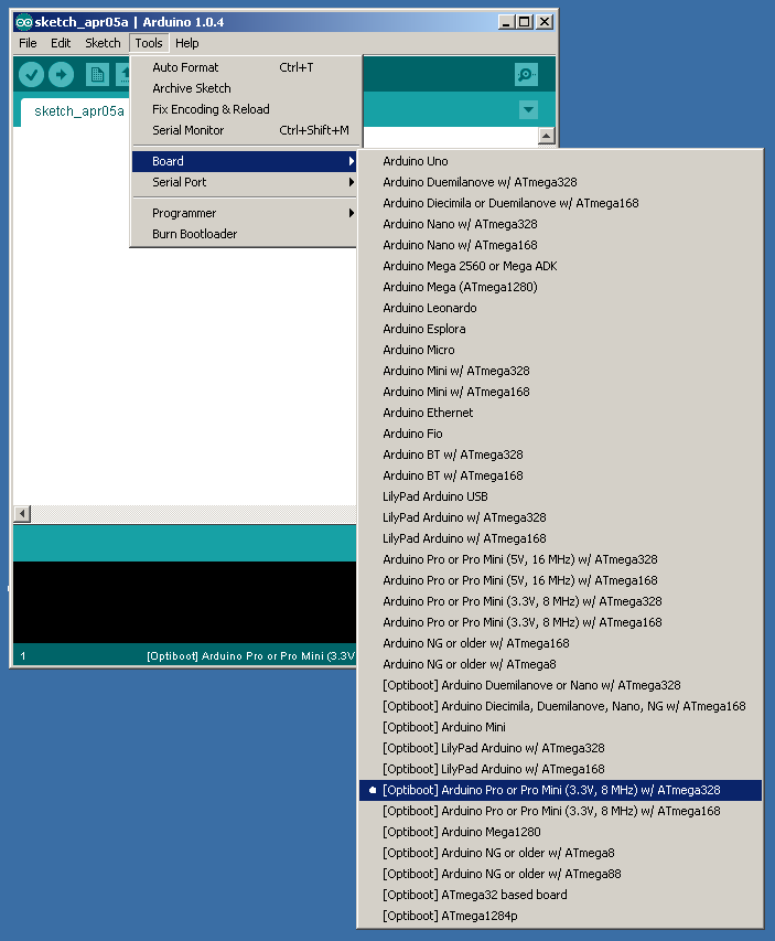
 That is it!  Restart the Arduino IDE and under the tools/select board menu you will now see:


There you go!  See that Arduino Pro or Pro Mini (3.3v, 8Mhz) w/ATmega328 can now be selected using the the legacy bootloader, or you can pick the new Optiboot one (as shown).

In use you need to select the bootloader you wish to use when flashing it in (See: http://arduinoalternatorregulator.blogspot.com/2013/12/33v-boot-loader-for-arduino.html ) and make sure to pick the SAME board when uploading sketches.

There you go!  Not only do we get to support 3.3v, the watchdog, and we got more programing space.  What is there NOT to love??

(Well, as long as we are adding target environments, how about this one:  http://highlowtech.org/?p=1695
Mini Arduinos!!!)