==============================================================
Generation 2 regulator only
Assembly
 Use the resources in the above tabs to guide you during the assembly of the PCB. Make sure to refer to the errata for each release (Posted with the schematic above), as well as check out this link for additional hints and details.
ArduinoAlternatorRegulator.blogspot.com/../pcb-errata.html
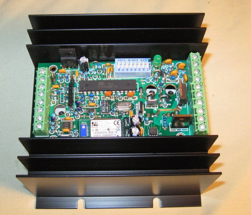
Once assembled, you will need to drill mounting holes in the heat sink and using TO-220 insulators screw on the PCB to the heat-sink.
I run a 6-32 tap through the 4x mounting holes on the PCB, and then bring a machine screw up from the bottom of the heat-sink and carefully tighten them using 1/4" spacers between the PCB and the heat sink as shown here:
 |
| Showing mounting screws and hardware |
Make sure to also mount the 3.3v regulator on the top side of the PCB (U1) to the side of the heatsink as well.
Loading Bootloader and Firmware
Setting things up.
To install the program, you need to download the Arduino IDE. Click on the 'Arduino' resource tab above and download the software to your local computer. Also download the following:- Libraries from the Arduino Lib tab, place these in your local lib directory (user/arduino/lib on a windows machine)
- Source code from Source Code tab. Place it in your local sketch directory (user/arduino on a windows machine)
- 3.3v bootloader from the Arduino Lib tab (select the SmartRegBoot folder and follow the instructions in the Readme.txt file).
Once you have done this you can open the arduino IDE. Then under "Tools/Board" select the 'Smart Regulator (fixed Optiboot - 3.3V, 8 MHz) w/ ATmega328p'.
Burning 3.3v bootloader
Before a sketch can be downloaded to the ATmega CPU, the boot loader needs to be installed (if it has not already been done). TURN OFF ALL THE DIP SWITCHES ON S1! ( Specifically DIP1, 7 & 8 ) Then following directions here to install the bootloader:arduinoalternatorregulator.blogspot.com/2014/06/burning-arduino-33v-8mhz-atmega328p.html
Loading the Firmware
Now you are ready to compile and load the Arduino Alternator Regulator sketch (or program). Referring to the 'Arduino Alternator Regulator' documentation you downloaded above, read the section titled: "COMMUNICATING WITH THE ARDUINO ALTERNATOR REGULATOR" on how to connect a 6-pin Serial USB to TTL adapter to the regulator. You can use other serial adapters, but note the Arduino Alternator Regulator is a 3.3v device so make sure your adapter is compatible.In the source code you can adjust some of the hardware features, for example: Define how the Feature_out port should be used (Lamp, Combiner, Charge Finished, etc). You can also change any details beyond what is allowed with the ASCII commands.
Note two #define switches: TESTING and DEBUG. TESTING will run regulator in a simulated mode - allowing bench testing of most new code modifications. DEBUG will enable additional ASCII status reporting with internal details, see the source for more information on this format.
=======================================================================
Hints for loading code using Mac OS X
(Thank you to Terry Slattery for providing these steps)Install Arduino IDE
- Downloaded Arduino.app and installed it in Applications.
- Install the CPU Support files from the 'Arduino Libs' resource tab above
- Install the Libraries from the 'Arduino Libs' resource tab above.
- Download latest firmware from the 'Source Code' resource tab above.
Install Silicon Labs CP2102 chip driver
Check what type of USB-Serial device you have - probably by checking the chip on it. It may be a Silicon Labs CP2101, an FTDI, or Prolific PL2303. You may need to load the drivers for whatever chip type you have, so be prepared to do some Internet research to find the appropriate drivers and load them on whatever OS you are using. (Note: The suggested USB <--> TTL adapter uses the CP2102 driver chip)CP2102 drivers for Mac OS X are available from their web site.:
https://www.silabs.com/products/mcu/Pages/USBtoUARTBridgeVCPDrivers.aspx
But the kernel extension wouldn’t load. I researched and found this:
https://github.com/nodemcu/nodemcu-devkit-v1.0/issues/2
Part of the explanation is that the USB cable didn’t work - some are made only for power. When I plugged the USB-Serial adapter directly into the Mac, the kernel extension loaded. (Hint: make sure the USB extension cable you purchase is a true USB cable, not jsut a power extension cable)
Check with kextstat and look for ‘silabs’ in the output (it should be the near the bottom.)
148 0 0xffffff7f8359d000 0x6000 0x6000
com.silabs.driver.CP210xVCPDriver (4.1.1) CF83A369-EA70-3E24-B8FE-7351DCF03430
<136 45 4 3>
A serial device was also created in /dev:
crw-rw-rw- 1 root wheel 31, 11 Jan 2 16:41 /dev/cu.SLAB_USBtoUART
Compiling the firmware
In the Arduino IDE (v1.6.6), do the following in the GUI:
Tools->Ports and select the USBtoUART port.
Tools->Board and select the Smart Regulator Fixed Optiboot board
Connect the USB-Serial board to the Smart Regulator board. I used individual 6-inch jumpers. This allowed me to plug the USB-Serial board directly into my MAC to avoid questions about the USB extension cables I have. A better connection can be made with a ribbon cable. I made up a 12 ft cable using an old Cat 5 cable to extend the serial link to the board from the USB interface. No need to use a USB cable in this case. The cable needs all wires (the DTR line broke at one point and it is the line that tells the board to reset). Also use the 3.3v line to power the board instead of using an external power supply.
Load the Blink sketch into the Arduino IDE. Change the LED port to ‘8’ from ’13’and click on the UpLoad button. It should compile (I had some warnings about deprecated paths). It also stated how much program storage was used. I looked at the LED and it was blinking. To verify it, I changed the timer value and saw that the LED blinks at a different rate.
Start Arduino.app. Make sure that the Board and Port are properly set under Tools. Load the SmartRegulator code file (I have several - orig, debug, and another). Then click on Upload to load it.
Loaded the Smart Regulator code. No problems there. I then used ZTerm to connect to the SLAB_USBtoUART port and immediately saw alternator status messages (AST) from the smart regulator. It resets itself on a timeout if it doesn’t see a battery voltage on VBatt+ and VBatt-. I jumpered VBatt+ to Enable and connected a small 12v battery for initial testing. Temp sensors are connected and they change as I heat and cool them with my hand.
No comments:
Post a Comment
Note: Only a member of this blog may post a comment.