(Last edited April 15, 2014)
The following describes the major subsections of this Ametel / Arduino alternator regulator. See the tab above 'schematic' to download a full view .pdf file (or the KiCAD files once I finalize the design). Much of the design is influenced by the need to cover a wide range of operating voltages, from as low as 8v in the case of a depleted 12v battery, to an extreme of 70v which might occur in some cases when equalizing a 48v battery. Major subsections are divided into:
- Power Supply
- Battery Voltage and Current Sensing
- Temperature Sensing
- Other Input and Output
- Alternator Field Drive
- Communications
- Protection
The below represents v0.1.0 of the hardware design. Before I go to PCB fab I want to look into simplifying things to a 3.3v only design, but need to research the Arduino programing environment to see if it will allow for that...
Power Supply
The Power Supply has a kind of challenging situation. Between the wide input voltage range needed, the potentially noisy (electrical) environment, and perhaps warm engine rooms - coming up with a solution took a couple of tries. The baseline requirements are:
Vin = 8v - 70v
Vout = 12v @ 1-2mA (Charge Pump feed)
Vout = 3.3v @ 70-100mA
The wide Vin range spans engine starting conditions on a rather weak 12v battery, to equalizing of a 48v battery. Turns out the 70v high point limits the available range of regulators greatly. Very few can work above 60v...
For this design I selected a cascaded linear regulator design.
 |
| Sequential Linear Regulator covers Vin of 8V to over 70v. |
The BDX53C is rated for Vce of 100v and will do the bulk of power drop and heat dissipation. It will deliver just over 12v under most conditions, tracking Vbat-2v in very low voltage situations (ala very discharged 12v battery where Vbat = 8v). To handle potently large power dissipation it is mounted to the heat-sink in the same way the field FETs are. The resulting 12v is used to both pre-regulate for the 3.3v LDO and to feed the Field FET charge pump. The 3.3v LDO will also need to be mounted to the heat sink in order to gain a bit more thermal headroom. If just doing Free Air, keep ambient temperature under 120f.
Of special note is C22 - the 0.1uF cap across the zener diode. The thinking here is to take advantage of the Hfe inside Q1, in effect 'amplifying' the noise-cutting ability of C22. During a noise imunity Spice simulations, adding in C22 cut in half the amount of noise passed through to the LDOs; to less than 5mV noise into the LDOs when presented with 100V of white-noise on Enable! Noise out of the LDOs was shown at 15uV. I think this will be a nice and quiet power source, even with massive amounts of noise on the supply feed. The zener diode D13 is actually part of the protection ckt - see Protection section.
D16 provided reverse voltage protection, while D13 is part of the input over-voltage protection ckts. (See section on 'Protection' for more details..)
Battery Voltage and Current Sensing
A core function of any alternator regulator is the accurate sensing of battery voltage, it is afterall what is 'regulated' in a voltage regulator! When I was researching battery voltage sensing for the Integrated Controller and Regulator project I looked at lots of examples, most of which centered around using resistor dividers to bring the 12-17v battery voltage to under 5v and then using the native A/D converts of the Atmel CPU. This simple and effect way when combined with some software filtering will give reasonable insight into the battery voltage. But there is a major flaw with this approach: Resolution...
When regulating the battery voltage I wanted to keep it tight. For example, in a 12v battery we might want to regulate the top voltage within the range of 14.4v and 14.5v, or 100mV (in fact, I actually regulate tighter than that - to a 25mV range). If we used a 4:1 ratio voltage divider to pre-scale the battery voltage, this 100mV range is reduced to 25mV when presented to the Atmel A/D converter. Now, the Atmel A/D converts are 10 bits - or 1024 discrete steps.. Given a range of 0v - 5v, that works out to around 5mV per bit. So you can see, despite starting with 10 bits of A/D resolution, once we start to focus on the range of voltage we are interested in we end up only having 2, or maybe 3, bits of usable resolution. That is the issue. Trying to do tight regulation with only a few bits of relevant information. Throw some noise in there and one can see how this is perhaps not the best approach. And if we extend this divider to cover all the way up to 70v, well we will end up with not even 1 bit of resolution.
One can add op-amps to scale and level shift and after looking at that I went a different way. TI offers a series of really nice voltage and current sampling devices, ala the INA-220 or INA-226. These are I2C devices, have great resolution, cover a wide range of voltages, and can even do a lot of the oversampling / averaging themselves! For this regulator I selected the INA-226 device. It is natively tolerant to 36v and its 15 bit A/D gives us a 1.25mV resolution per bit! And they are cheap, under $3 each and in the end less cost then the discrete OpAmps approach. A pre-scaling resistor divider is still needed to cover the whole voltage range up to Vbat of 70v, using a 2:1 ratio still gives me 2.5mV single bit resolution in VBat measurements.
(Side note: Another reason for selecting the INA-226 vs the INA-220 was problems I had around using high-impedance resistor divider networks to pre-scale VBat. The INA-226 has a nominal input impedance of 830K-ohms, vs the 320K of the INA-220. Making for less of an impact to the accuracy of the divider resistor R4/R10)
 |
| (Note: R24 has been changed to a 220ohm value) |
A key differentiator of this regulator is the the management of Amps in addition to Voltages. Primarily to measure the true state of charge of the battery. The INA226 is also capable of very small differential measurements needed to read our 75mV current shunt. As with the voltage measurement side I needed to do some pre-scaling work to accommodate amp shunts which might be installed in the + line on 48v systems. The INA282 does this by changing the differential voltage into a single ended voltage, and then referencing that to ground. Unfortunately for my purpose it also has a 50x amplifier, so I need to run that through a 50:1 resistor divider (R24 is actually 220ohm resistor in the final design) to get the voltage back into the 75mV range for the INA-226. In this case I could have instead directly feed the INA282 into an Atmel A/D converter, but I decided to run it through the INA-226 to take advantage of all the over-sampling capability built into the INA-226. No need to re-do it in software what is already there for free...
Take note that the reference pins of the INA282 are connected to +3.3v vs. Ground. Doing this sets the 'zero current' point around the 3.3v level and allows the INA282 to pass forward negative currents (that is, currents being drawn out of the battery). Helpful when looking to decide if we need to exit Float mode..
Temperature Sensing
Battery needs are rather temperature dependent. Their target voltage can very much depending on the battery temperature so adding a temperature prob is a common and very good idea if one truly wants to treat the batteries right. It is funny how often commercial regulators make a big deal over temperature adjustments, as for FLA batteries the logic is rather simple:
setPointVolts += (77-batTemp) * 0.0168 ;
Yup, adjust target voltage up or down 16.8mV for each cell in the battery.. E.g., 6 cells in a 12v battery = 0.1V for every 1f degree above or below 77f. So, the code is simple, the challenge is doing the actual measurement For this design I selected to use NTC 10K thermo probes Simple and reliable, and this time I did use the built-in Atmel A/D converters:

A resistor divider is formed between the nominal 10K temperature probe and the 10K resistors R12 and R15. C6/C7 do dual functions of forming a low-pass filter to cut out the bulk of noise (any remaining noise is filtered out in software via oversampling), and they also provide a lower-impedance input into the Atmel CPU. And here is a little side trip: The Atmel A/Ds is actual one A/D with a switcher at its input. This switcher can select one of the external ports at a time or a couple of internal points, ala CPU temperature! Code: AnalogRead(port#) causes the Arduino libraries to switch to the requested port and then starting an A/D process. The A/D does this by taking a snapshot of the input voltage and saving it into a temporary working capacitor. Then it works from that snapshot capacitor to produce the A/D digital value. And here is the rub: If the incoming single has a high impedance it can take too much time to bring this internal snap-show capacitor up to the actual voltage - we have infect created yet another low-pass filter with a long time constant (R*C). Ref section 24.6.1 in the Atmel datasheet (" Analog Input Circuitry") - where it recommends Zin be 10K or less. Truth be told we are likely OK with the nominal 5K impedance, but C6/C7 will make sure we get good stable readings when selecting and doing the A/D conversion. Plus they filter out a lot of unwanted noise...
R16/R17 and the diodes attempt to give a little protection to the CPU from any voltage spikes, the PTC poly-fuses are there in-case one of the probes is shorted to a battery voltage. (See Protection section for more info). Finally, R7/R14 provide a little decoupling from ground of any noise that might be picked up by the NTC leads.
While I was add it, I put in an Alternator temperature probe. This will be used to pull back the alternators output if it starts getting too warm, and faulting if it gets into the danger area.. (BTW, the code also faults if the battery temperature gets too high, approaching the point of a runaway risk)
Other Input and Output
Feature In/Out and Stator Sampling complete the sensing portion of the design.
The 8-position DIP switch is the primary way the user can configure the regulator, for battery size and type as well as alternator derating options. These are directly wired to the Atmel CPU where I rely on the internal Pull-up resistors to sense if a switch is open or closed.
Feature-in is brought in via a current limiting resistor R8 and clamped for a safe voltage by D10/D20. R3 acts as a pull-down in case Feature-in is left unconnected, and also as a pre-scaling divider to help reduce the current D10 needs to conduct, esp in 48v systems. Feature-out is a simple logic level FET, R34 makes sure the FET is in an off-state during that time between power-on and when the Atmel CPU get booted.
For the stator sampling I used the same circuit I used on the integrated engine controller and regulator. R30/D21/D14 again form a limiter / clamper while R30/C18 form a low-pass filter with a knee frequency of 800hz. Sampling a Stator allows me to lock-step VBat measurements with a stator pulse, resulting in greater accuracy and consistency of voltage regulator. It also lets me do a RPM calculation as long as the alternator is charging. As all I am looking for is to provide an Interrupt signal to the Atmel CPU (interrupting on a rising edge), this circuit works well. But it has a threshold voltage of around 2.4v. If one wanted a more sensitive stator sample, doing an op-amp pre-conditioning and edge sensing would allow for stator sensing even during no-field conditions by sampling the small stator waveforms as a result of residual magnetism.
Field Drive
The other core function of an alternator regulator is to drive the Field, and in microprocessor based designs using PWM is common. I had three primary goals I wanted from the Field Drive:
- Support for HIGH drive and LOW drive (P and N-type) alternators
- Support for Field Currents up to 20A, allows driving of two or even three alternators in parallel
- Support for Field Voltage from 12v to 48v, independent of the rest of the battery / system voltage.
Point #3 is perhaps one of the key differentiators of this regulator vs. anything else available. It allows you to use say a 12v alternator to charge a 24v battery. The Field stays 12v, but the battery voltage sensing and such are 24v. Many people are doing this with great success, ala the LN555 type alternator. It also allows one to have say a 12v engine driving a proper 48v alternator. Lots of flexibility. I had accomplished these goals in my integrated engine controller and regulator by using a large number of stuffing options, but wanted in this design to make it self-adjusting.
Goal # 1 is meet by using N-type FETS in combination with a floating driver chip combined with a series of external wiring jumpers (A, B, C, D) to configure for HIGH drive or LOW Drive. The FETs I selected (Q2 and Q4) are good for 100V and 33A each. Running in parallel we can support massive amounts of field current, and the modest PWM frequency means there is little switching loss, hence little heat.
The FET driver is perhaps the most interesting part. Using a common floating Boost-driver chip to drive the FETs allowed not only the selection of low cost / high performance N-Channel parts, but also decoupled the FETs from the drive logic level and allowing jumpers A-D to be used to configure for P or N type fields. A fly in the ointment with these Bootstrap drivers is they all require some level of PWM frequency be present at the Field PWM signal to drive the internal charge pumps. This meant I would not be able to push the field to Full Field drive.
I did locate one part, LT1910, that solved this nicely by having a built in oscillator independently drive its charge pump. I used this in the initial design and it works like magic. However, it is only good for up to 60v, a bit too low to support a 48v battery system during equalization (which can reach 68v for FLA batteries). My options were:
- Use the LT1910 and restrict 48v system to not equalize
- Use the LT1910 and restrict 48v systems to only equalize with LOW drive Fields
- Use a different part, allowing flexibility and equalization in 48v deployments, but prevent Full Field...
An additional benefit to the last option is the LT1910 is really an odd-duck. I was not able to locate ANY other FET driver with its own built-in oscillator, while other driver chips are a dime a dozen.
After thinking about this for a while I decided to build my own charge pump and drive it by a separate PWM signal from the Atmel CPU. In this way I can develop the needed boost voltage to drive the FETs, while also allowing for full PWM field drive. I found an interesting approach of configuring a FET (Q6 above) to self-switch, eliminating the need for an inverted PWM driver with all its associated issues of race conditions. (reference: "A Self-Boost Charge Pump Topology for a Gate Drive High-Side Power Supply" by Park and Jahns. IEEE March 2005). Building upon this in operation when Q5 is enabled C12 will charge to around 11v via D9, R19, and D11. When Q5 turns off, R9 then starts to bleed some of that 11v back to the net named 'Floor'. This starts Q6 to turn on as we now have the 11v in C12 applied across Q6's Gate-Source (with D11 now blocking the bead-back).. As Q6 turns on, it pulls the Floor up to the level of the main FETs Source (Vs on U3), pushing C12 up with it via R19. Resulting in the 'Pump' net to ultimately be sitting 11v above the floor - transferring this charge pump voltage into C11 via D8. R19 is in place to limit peak surge current, protecting both the FETs and the Diodes.
D1/D5 give flyback protection.
Communications
There is a need to communicate with the regulator in order to load its firmware. This is accomplished by a serial port that can be attached via the Service connector. I expanded the firmware to take advantage of this communications path to also send out status information for operation as well as debug. Inbound communications can be used to configure all the feature of the regulator beyond what the DIP switches allow.
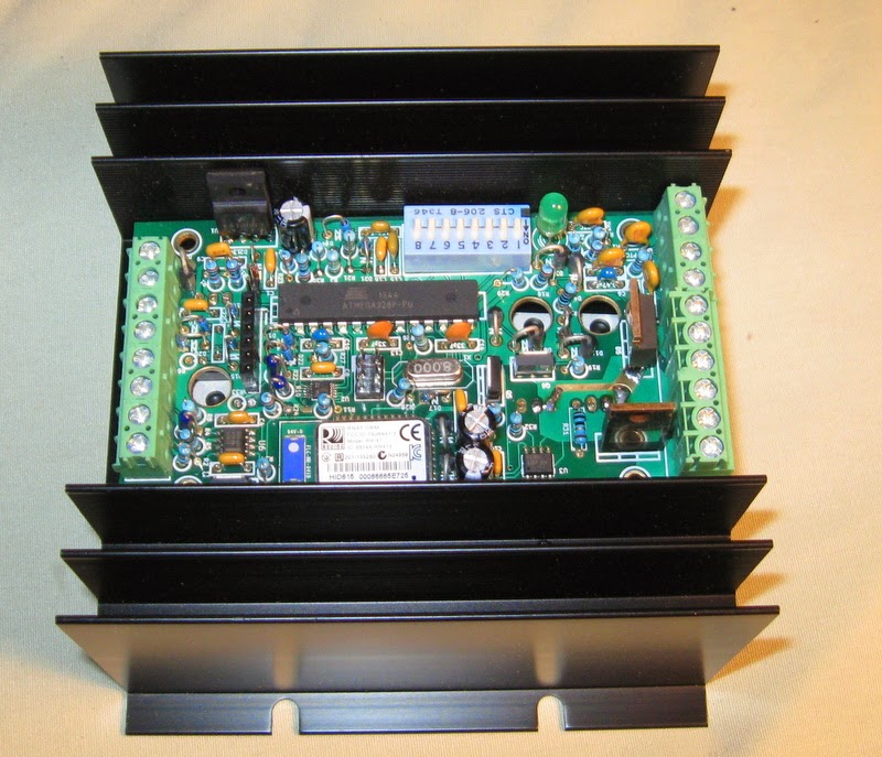
In parallel with this TTL level serial port I attached a Bluetooth module configured in the SPP mode (Serial Port Profile). This does nothing more than provide for a wireless link of the same serial information available via the hardwired serial connector.

The pin header SERVICE pinout matches that of a low cost USB-TTL adapter. R6/R33 and D15, D17, D19, D22 provide protection to the CPU. The Bluetooth module U6 is connected to receive serial information via the voltage divider R37/R38 - bringing the 5V levels down to 3.3v. R28 gives a soft coupling into the transmission side. The ratio of R28/R6 assure any attached hardwired serial adapter board will have priority in sending data to the CPU, while allowing the Bluetooth modules communications to get through in the case of no attached external module. R27, C19, D18, along with the internal 10K piull-up inside the RN-41 module make up the coupling of a Reset signal as provided by the external USB--TTL adapter and the Arduino programming environment. Special note: The Atmel CPU reset pin is very over voltage tolerant. D18 is there to protect the RN-41 module, which is not as forgiving. Note also the dramatic change in C19 with the presence of the internal 10K pull-up in the RN41 module.
Finally, R29/D12 give a way to communicate status and error situations to the user in the case that no external terminal is attached.
Protection
Protecting the Atmel CPU from voltages greater then 3.3v falls primarily to the use of relatively high value series resistors backed up by a pair of low-Vf diodes. R30 + D14/D21 in the Stator input line are a prime example. (The addition of C18 is really there to filter out noise, though it can provide a small degree of protection from high frequency spikes). I had tried to use Zenor diodes instead of Diode pairs, but the knee sharpness of low voltage zenors are really bad, and I eventually ended up with massive leakage. So I went to nice clear dual schottky diodes.
One downside of this (and an advantage of using the zeros) is the Diode to +3.3v introduces noise into our nice and clean Vcc.. This noise / over-voltage is absorbed by the normal 3.3v power usage fo the regulator, and adding extra bypass caps helps. Another risk is too much 'over-voltage' induced current, more then the board can use, may result in the 3.3v line starting to rise above 3.3v. Example, if the battery NTC temperature probe made contact with a 48v battery, D6 would shunt the excess voltage into Vcc (3.3v), but R16 would only limit the amount of current to 203mA, well over the 100mA or so total current draw of the board. Here is where the large 3.6v Zenor D13 comes into play, to shunt that excess current to ground until one of the poly fuses can blow. As with all designs, there are trade offs. Other approaches using Op Amps, or PNP active shunts, etc would provide a bit more protection, but add costs and PCB board space.. Overall, I think the protection in this regulator will work well for all except if someone truly sets out to let the magic smoke out! (ala, applying 220v AC likely will be a bad thing).
dkdkd


