And the schematic can be found in the Schematic Link above. BOM/shipping cost came in at $83 for the regulator and just under $100 for everything: Regulator, Temp probes, Current Shunts, etc. All but connection wire and fuses.
The basic concept for this regulator is the same as the integrated Engine Controller and Regulator, with a few differences:
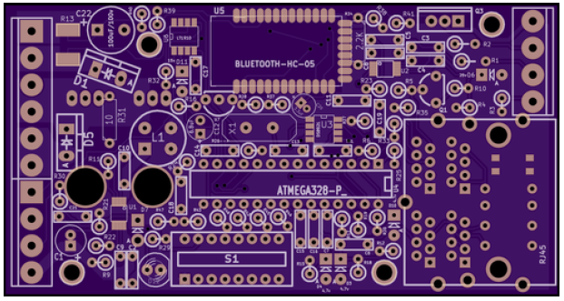
- Found a simplified FET boost-driver (LT1910) that has a built in Booth PS. It should allow N-Channel FETs to be used from 12v to 48v on P or N type alternators w/o any hardware changes. Will be interested to see how it works!
- Have eliminated the hardware remote LCD panel, the unit will just start when power is applied and optionally communicate status via Bluetooth. (Or the built in Serial port)
- Have on board DIP switch and LED for stand-alone configuration and operation. Just select the battery type, size, and some other special features and connect it up. Nothing else is needed to get it to work in its basic function.
- Sync port to coordinate functions between two regulators charging the same battery, ala in a twin engine boat. Mostly this is to share Amps produced, but as the firmware progresses, might find other needs for this coordination.
I should be picking up the parts late June, early July. Then will be building them up. Till then, I continue to use my Fixed voltage truck regulator on the main house battery alternator, and the integrated Arduino controller on the Generator.
No comments:
Post a Comment
Note: Only a member of this blog may post a comment.