- PCB
- Electronic Parts
- Heat Sink
- USB --> TTL adapter board (optional)
- USB Male – Female extension cable for above
- ICSP programmer w/6-pin adapter
- 4x TO-220 Insulated mounting hardware
- Thermal grease
- Mounting hardware
- 4x #6 x 3/4" pan-head machine screw
- 4x #6 x 1/4” insulating nylon standoffs
Total cost for all of the above should be will under $100, and much lower depending on if you implement Bluetooth or not.
PCB
I often have a supply of PCBs available, see the right to check that status. Alternatively you can use the resource tabs above and download the latest GBR files to be used with the PCB fabricator of your choice. (or the CAD files, make mods as you wish and go from there!) When making up the PCBs I use standard thickness and 1oz copper, you can consider upgrading to 2oz copper if you expect to drive high field current (or perhaps two alternators in parallel). Alternatively, there are open places in the solder mask which can be used to 'reinforce' the field drive traces - just solder on some short wires in those spots to help carry any field current.ELECTRONIC PARTS
For convenience I use Mouser.com for sourcing my parts - to be honest, mostly because they seem to not mind too much (or at least do not complain too much) selling small quantities of parts, and their web page is a bit better then other supply houses when it comes to locating and comparing components. Under the resource tab 'Parts List' above you will find a .xls sheet with the BOM, I also have places a 'scrubbed BOM' at Mouser.com (as of December 2014) that can be access using this link:https://www.mouser.com/ProjectManager/ProjectDetail.aspx?AccessID=f0133335ad
Do note this mouser BOM is for v0.1.4 of the PCB and includes the Bluetooth module. If you wish to not use the Bluetooth, make sure to check the schematic for part changes - specifically:
- Do not order the RN-41 Bluetooth module
- Replace D18 with a 10K resistor
- Change C19 to a 0.1uF capacitor
And of course there are other sources than Mouser.com - nothing magic about anything in the board - do take note the 8Mhz crystal picked uses 33pf loading caps (it was what was available when I 1st selected parts for this project), if you select a different crystal - make sure to match up the loading caps C13 / C14 to the specs of the crystal.
HEAT SINK
Perhaps the hardest part to source. The Arduino Alternator Regulator really does not produce that much heat, but a small amount of thermal capability is needed - mostly on Q1 and U1. When designing this I selected a heat sink largely for its physical protection. The part I designed to is a: Hongfa HF92B-120 (http://octopart.com/hf92b-120-hongfa-19677676). It is designed to support a couple of SSRs (Solid State Relays) and was selected due to its large flat space in the middle. In fact, the PCB is designed to fit this space with an overall size of 105mm x 55mm. The problem is this part is a PITA to source - and my experience with the one supplier out of Australia is a little less then positive - esp with regards to shipping costs. So, here is some additional data for you and some ideas for alternatives:Heat Displacement of the regulator is documented here:
http://arduinoalternatorregulator.blogspot.com/2014/04/confirming-power-dissipation.html
In most cases, it will be rather modest. Some ideas for alternatives heat sinks might include:
- Modify more commonly available heat-sink, removing a fin to get a bit more width if needed.
- For example: Orman - Y92B-A150N
- Wakefield 423K
- Any Fine Type heat-sink.. Look on Ebay, local supply house, scrap bin
- Utilize some extruded 'L' shape aluminum stock?
- A die-cast metal box?
COMPUTER ADAPTERS
There is one adapter you will need, and one more you likely will want. Because a custom boot-loader is needed (a 3.3v opti-boot), you will need to gain access to an ICSP tool. And ideally a 3.3v capable one. I use a widely available open-source tool based on the USBasp. It should be available off of EBay for under $5 or so, make sure you have some way to get to the 6-pin ICSP connector used by the Arduino Alternator Regulator (Either via an adapter board, or just some jumper wires as I use). There are a few more details involved which I have documented here:http://arduinoalternatorregulator.blogspot.com/2014/06/burning-arduino-33v-8mhz-atmega328p.html
Make sure to note the need to have a good solid 3.3v power source while burning the bootloader - (a USBasp by its self will not be sufficient) Either hook up the regulator's Enable pin to an external power supply, or you can get sufficient current if you also use the Serial Service Port adapter described next.
The other board which you might find helpful is a USB <--> Serial adapter board. Once the Bootloader is flashed in you can use this board via the Service Port to load sketches. It also provided a way to gain access to Serial ASCII string status outputs as well as a way to send ASCII commands to the regulate - if you do not wish to use the Bluetooth module (or wish to 'override' it temperately). I have designed the regulator to directly connect with certain 6-pin adapters - and I selected those adapters as they are able to supply 3.3v as well as 5v without any switches or jumpers needed. In this way, all my projects use the same adapter board and you do not need to worry about setting switches. Take note this is NOT the same pin-outs as used on the small Arduino boards...
I purchase mine from Ebay for around $2 each using the search string: “CP2102 USB 2.0 to TTL UART Module 6Pin Serial Converter STC Replace FT232” . If you take care to get one with the pinout of this spec you can directly plug it into the Service Port:
- DTR
- RXD
- TXD
- +5V
- GND
- 3V3
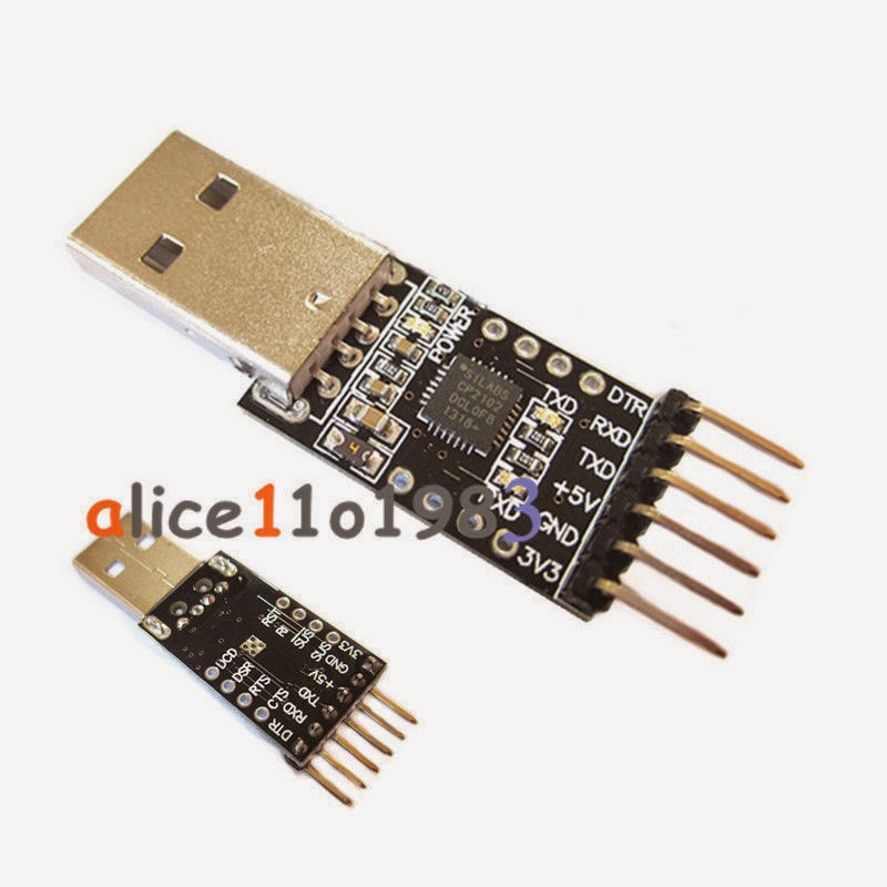 | |
| Example of 6-pin adapter with correct pin-outs (Click on picture for larger view) |
Of course other serial adapters can be used (you can even pull the ATmega328 out of an Arduino UNO and use that) - you will just need to match up the pins. You do need to make sure you can get access to the DTR signal, as that is used by the Arduino IDE to reset the uC and allow sketches to be loaded. Do not confuse this with adapters which have a pin labeled 'reset' or 'rst' - often those pins are used to reset the USB adapter, and will not work with the Arduino IDE without modification.
MOUNTING HARDWARE
Finally you will need some mounting hardware. TO-220 insulating hardware and screw sets. Mouser has them (e.g.: 534-4724 for a couple buck each), or you can order in bulk - myself I again look to Ebay! Make sure to get some thermal grease as well.To mount the regulator to the case / heatsink of your choosing you can use nylon standoff spacers that match the off-set you used when soldering in Q1, Q2 and Q4 (the TO-220 parts mounted on the bottom of the PCB). Used 1/4" - because in the USA 1/4" nylon spacers are easily found. But of course you can use what you wish. The 4 mounting holes in the corners of the PCB are 0.120" in diameter (approx 3mm). I found they are just right to allow taping for a #6 machine screw - a 3.5mm machine screw should work just as well. I then just ran a machine screw up through the underside of the heatsink, put on a spacer and gently screwed it into the PCB - letting the PCB act as the 'nut'. If you want you can add threaded nylon spacers to the top of the PCB, screwing onto the protruding stud and perhaps that can hold some type of overall cover. To see a bit more details on how I mounted my regulator, click here:
http://arduinoalternatorregulator.blogspot.com/2010/06/assembly-and-programming.html
Hi, not sure if my last reply got through, internet here in Grenada is poor. By chance would you sell me 2-3 pre-assembled units? I would rather not have to assemble on the boat.
ReplyDeletebtw, I see you are installing a lifepo4 battery system. I designed/installed mine about 2 years ago. It is 24v/800aH and runs my cabin aircon all night with need for a genset. Not thrilled with my passive BMS so I am investigating an acitve balance/charge system now.
Cheers,
Rick
Just to let folks know, Rick and I did connect via Email. (See About Me on Right). I do not at this point have assembled PCBs, but know it would be nice to have that resource available. Maybe in the future...
DeleteHello, I am wanting to build one of your Arduino based alternator regulator. I am wanting one for a test stand use, hoping to use one regulator to test a variety of alternators, 14, 28 and 56 V DC. I have board house connections for populating a PCB. I will send you an email for the blank PCB. Want changes are needed to test a variety of voltages on alternators? is it a manual adjustment or programming?
ReplyDeleteHello. Did receive your Email, and will reply there as well. To your question here: the code attempts to automatically determine which 'voltage' the system is during startup by looking at Vbat. This will set a voltage multiplier to be used to adjust internal voltage set points from the 'normalized' 12v ones. Example, if one had a 24v system, the multiplier would be 2. If one had a 32v system, the multiplier would be 2.6667
DeleteThe voltage multiplier being used is reported out via the 'SST;' ASCII status string. Refer to the reference manual and note the entry 'BC Mult' in the SST string.
This multiplier can also be overridden and set to a hard value via the $SCO ASCII command string (again, refer to the users guide). Once overridden the regulator will use that value as opposed to attempt to auto determine.
Perhaps this will give what you need?
Do you have a BOM for the V0.1.4 with the designators listed?
ReplyDeleteThank you,
Hello - yes, see the link to mouser.com above under "ELECTRONIC PARTS". Other option is to look under the resource tabs at the top of the blog - the tab labels 'Parts Lists'
DeleteHello Al,
ReplyDeleteI do see the BOM for the V0.1.4. The other BOM list the "designators" for where the components go onto the PCB. The V0.1.4 does not have the designators for locating components onto the PCB. Please advise. Thank you
Adam, so sorry! I just now edited the .xls BOM under the resource tab above to add back placement details.
ReplyDeleteThank you for bringing this to my attention, and sorry I did not 'get it' with your prior comment!
I would like to purchase a couple of boards im on my second attempted to build my own been following for a while. i have a 42' Californian LRC built arduino based fuel management battery management and autopilot using QT for user interface will send screen shots and source if anyone interested. also im not so good at surface mount soldering is there some place or one where this can be done
ReplyDeleteHello! Well, this winter I am looking into doing a build of the new design getting the parts professionally SMT soldered. Please send me an Email at:
Deletemv Viking Star @ gmail.com (Removing all the spaces)
and we can get things going. You might also join the mailing lost (See right side of blog) - as I will be sending out detains on that as we get closer.
Would like to hear more about your fuel and AP as well! Please do send me an Email, there seems to be no way to find your address just from the comment posts..
Hello,
ReplyDeletehttps://www.mouser.com/ProjectManager/ProjectDetail.aspx?AccessID=f0133335ad
some components no longer exist; by what can they be replaced?
Mathieu