Friday, June 28, 2013

Charge profiles - Need help in setting the Default ones...

A new feature of the standalone regulator is built in charge profiles selectable via the DIP switches.  There are 8 positions which can be chosen.  Each charge profiles contains parameters for a series of 'stages' with items such as :
  • Limits to Battery Voltage
  • Limits to Alternator Current
  • Exit criteria to allow moving to next stage based on Time, Current, or perhaps battery voltage.
  • Battery charastics, specifically Temperature compensation
Below is what I currently have for a 'place holder', and am open to input on the profiles as to be honest - mode are largely blank...  So, is there perhaps another battery that should be added?  (ala LiPro).  Should one or two of the spaces be held over for 'future expansion' in the default profiles?  Send me Emails (or post comments here) I would kind of like to have a 'standard' set of profiles and keep them for all revisions to the source, as I really do not want to get into a massive mixture of different source configurations in the field...


Normalized Charge profiles:

Before getting to the actual profiles, we need to understand how the regulator auto-adjusted for different battery voltages.  (12, 24, 36, or 48v).  To avoid making 8 profiles for each battery voltage, I decided to make all profiles  'normalized' to a representative 12v system small (500Ah) battery.   Then at startup the regulator will make two adjustments to the working charge profile depending on:
  1. Sensed Battery voltage.
  2. User selected 'battery capacity size' on the DIP switches.

The sensed battery voltage is applied to target Voltages (increasing them) while the Battery Capacity Size DIP switches are used to increase target Amps.

Example - currently the 1st charge profile entry for  Bulk/Absorption phase has the target VBat defined as 14.1v, and the 'exit' criteria (for exiting Absorption phase when the battery is truly fully charged)  is at 10a  (2% of the 500Ah battery capacity).  Two examples:  First a 12v large battery system then  a 48v mid-sized battery:


12v 1,600Ah battery:
  • Auto-sensing system voltage = 12v, multiplier is 1x.
  • User selected DIP switches  = On-On (1,500Ah or greater battery)
The regulator will adjust the run-time charge profiles as:
  • Volts  * 1x  - based on sensed battery voltage
  • Amps * 4x  - based on user selected DIP switch

So, the 14.1v / 10A  becomes -->  14.1v, 40A  Meaning the regulator will drive BULK mode until the battery voltage reaches 14.1v, then switch to ACCEPT mode - holding VBat at 14.1v until the measured current drops below 40A at which time it will move to the next phase (float in the case).


48v,  800Ah battery bank
  • Auto-sensing system voltage =  48v, multiplier is 4x.
  • User selected DIP switches  = Off-On (500Ah - 1,000Ah battery)
The regulator will adjust the run-time charge profiles as:
  • Volts  * 4x  - based on sensed battery voltage
  • Amps * 2x  - based on user selected DIP switch

So, the 14.1v / 10A  becomes -->  56.4v, 20A  Meaning the regulator will drive BULK mode until the battery voltage reaches 56.4v, then switch to ACCEPT mode - holding VBat at 56.4v until the measured current drops below 20A at which time it will move to the next phase (float in the case).


Charge Profile States:

Each charge profile has the following basic 'stages' or modes:
  • Ramping   - Initial state where the alternator is brought online slowly
  • Bulk         - Regulator will be in Bulk mode until the battery voltage reaches the Accept voltage limit.  During Bulk phase, Amps are limited by the capability of the alternator or optionally a defined max Amps.
  • Acceptance - Voltage is regulated to the defined limit.  Will stay in Accept  until Amps drops below the defined value (indicating the battery is fully charges), or a defined time limit is exceeded.
  • Float           - After Acceptance, this is a 'keeper' stage where the volts are regulated to a lower setting.

Each of these stages or modes have criteria for regulation of Battery Voltage and Alternator Amps, they also have exit criteria (exiting that mode and moving on to the next one) based on time, volts and/or amps being delivered.   There are also some additional stages:
  • Over Charge  - Between Acceptance and Float to give a final 'kick' to some battery types
  • Post Float      - Alternator is turned off letting the battery rest rest
  • Equalize         - Selected overcharging to rebalance the batteries


Charge Profiles:

Each Charge Profile (there are 8 of them, selectable via the DIP switches) has a series of entries to allow for targets and exit criteria, as defined by this structure:  You might find it easier to copy and paste this structure into a text editor of your own, to better be able to read the long lines.  Use a fixed-space font (e.g. Courier) to preserve tabbing and alignment.


//----- This structure defines a 'profile' for battery charging.  Each stage consist of 'modes', primarily:  Bulk, Acceptance, 
// Overcharge, and Float.  Each mode has a max voltage set point, and criteria for exiting that phase (Exceeding a time limit, 
// or Amps dropping below a given value).  Of special note is the entry Float and Post Float, which have additional criteria 
// resuming charging.
//


ACPT_BAT_V_SETPOINT;            // Set point for Ramp, Bulk and Acceptance battery voltage.  

                                // Alternator will transition from BULK mode into Accept Mode when this voltage is reached, and then start the Accept Duration counter.
EXIT_ACPT_DURATION;             // Stay in Accept mode no longer then duration in Hours
EXIT_ACPT_AMPS;                 // If Amps being delivered falls to this level or below, exit Accept mode and go to next (Overcharge)
                                //     Set ExitAcptAmps = 0 to disable Amps based transition and only rely on timeout duration.


                                // Overcharge mode is sometimes used with AGM batteries and occurs between Acceptance and Float phase.  

OC_BAT_V_SETPOINT;              //    Set point for Over Charge battery voltage (Set this = 0 to disable)
EXIT_OC_DURATION;               //    Over Charge mode duration in Hours.  (Set this = 0 will also disable Over Charge step.)
EXIT_OC_AMPS;                   // If Amps being delivered falls to this level or below, system will exit Overcharge mode and go to Float
                                //     Set this = 0 to disable Amps based transition and only rely on timeout duration.


FLOAT_BAT_V_SETPOINT;           // Set point for Float battery voltage

EXIT_FLOAT_DURATION;            // Alternator will stay in Float mode this many hours before entering Post-Float (no charging) mode.  Set = 0 disable transition to Post-float mode.
FLOAT_TO_BULK_AMPS;             // If Amps being delivered exceeds this value, we will assume a LARGE load has been placed on the battery and we need to re-enter
                                // BULK phase.   Set this = 0 to disable re-entering BULK phase feature


EXIT_PF_DURATION;               // Only stay in Post_float mode (no charging) this amount of time.  Set = 0 to disable times based Post-float exiting and exit only on Voltage.

PF_TO_FLOAT_VOLTS;              // If during Post-Float mode VBat drops below this voltage, re-enter FLOAT mode.   
                                // Set = 0.0 to disable exit post post-float mode reverting to FLOAT Charge mode based on voltage.
                                // Config note:  If you configure the system to enter post-float mode from float-mode (by setting the time value EXIT_FLOAT_DURATION), AND you
                                // set both EXIT_PT_DURATION and PF_TO_FLOAT_VOLTS = 0, the regulator will in effect turn off the alternator once charging is completed
                                // and not restart a charge cycle until powered down and up again.  This can be useful if you truly want a one-time only charge.
                                // You could also config the FEATURE-OUT port to indicate the complete charge cycle has finished, to say power-off the driving engine?


EQUAL_BAT_V_SETPOINT;           // If Equalize mode is selected, this is the target voltage.  Set = 0 to prevent user from entering Equalization mode.

EQUAL_BAT_A_SETPOINT;           // During equalization, system will limit Amps to this value.   Set = 0 will also prevent user from entering Equalization mode.
EXIT_EQUAL_DURATION;            // Regulator will not stay in Equalization any longer then this (in Hours).  If set = 0, then Equalization mode will be disabled.
EXIT_EQUAL_AMPS;                // If Amps fall below this value during Equalization, exit equalization.     Set = 0 to disable exit by Amps and use only time.


BAT_TEMP_1F_COMP;               // Battery Temperature is compensated by this factor for every 1F temp change.  Note this is based off of BAT_TEMP_NOMINAL (77f)

MIN_TEMP_COMP_LIMIT;            // If battery temperature falls below this value (in deg-F), cap temp compensation voltage rise to prevent overvoltage in very very cold places.
BAT_MAX_CHARGE_TEMP;            // If Battery exceeds this temp (in deg-f), stop charging and force into Float Mode to protect it from over-temperature damage.


Do I need some additional parameters?  e.g., should there be a Float-to-Bulk voltage set point in addition to the Amps value?


Charge Profile Entries:


And here is the 8 entry table that I have for the current 'charge profiles':  Take note that there are a LOT of blanks, for example Post Float and OverCharge are currently disabled for all entries.  And the Temp Compensation is all set to the FLA type battery, which I suspect is not the right answer.   So - -   If you have knowledge on this area, please send me comments to:  mvVikingStar@gmail.com  Thanks!


   Bulk/Accpt                Overcharge              Float                 Post Float            Equalization                Temp Comp   
{14.1v, 4.5hr, 10a           0.0v, 0hr, 0a          13.1v, 0hr, 0a            0hr, 0.0v,           0.0v, 0a, 0hr, 0a,         0.028*6/10, 15f, 125f}, // Default (safe) profile.
{14.6v, 4.5hr, 10a           0.0v, 0hr, 0a          13.4v, 0hr, 0a            0hr, 0.0v,         15.5v, 0a, 0hr, 0a,         0.028*6/10, 15f, 125f}, // Standard FLA
{14.1v, 4.5hr, 10a           0.0v, 0hr, 0a          13.6v, 0hr, 0a            0hr, 0.0v,         13.6v, 0a, 0hr, 0a,         0.028*6/10, 15f, 125f}, // Standard Gell Cell
{14.3v, 4.5hr, 10a           0.0v, 0hr, 0a          13.1v, 0hr, 0a            0hr, 0.0v,         15.5v, 0a, 0hr, 0a,         0.028*6/10, 15f, 125f}, // Standard AGM (1)
{14.5v, 4.5hr, 10a           0.0v, 0hr, 0a          13.5v, 0hr, 0a            0hr, 0.0v,         14.5v, 0a, 0hr, 0a,         0.028*6/10, 15f, 125f}, // Standard AGM (2)
{14.1v, 4.5hr, 10a           0.0v, 0hr, 0a          13.1v, 0hr, 0a            0hr, 0.0v,           0.0v, 0a, 0hr, 0a,         0.028*6/10, 15f, 125f}, // Reserved for future use??
{14.1v, 4.5hr, 10a           0.0v, 0hr, 0a          13.1v, 0hr, 0a            0hr, 0.0v,           0.0v, 0a, 0hr, 0a,         0.028*6/10, 15f, 125f}, // Custom #1 - Users Entry
{14.1v, 4.5hr, 10a           0.0v, 0hr, 0a          13.1v, 0hr, 0a            0hr, 0.0v,           0.0v, 0a, 0hr, 0a,         0.028*6/10, 15f, 125f}  // Custom #2 - Users Entry


Wednesday, June 26, 2013

Working through Bring Up

Have been making good progress on the bring-up, with many of the subsections tested.  So far have the hardware almost 100% 'spot checked' for no-smoke and some level of function.  Am now working through integration of hardware and software, and doing more detailed sub-section testing.

Here is a photo of the 1st board:


Notice I am using a Uno development board to provide DC power as well as communication to and from the regulator.  All those Tombstone resistors provide handy test points!


Wednesday, June 19, 2013

PCB and Parts have arrived!

Yesterday we stopped by our maildrop here in Friday Harbor and picked up a pile of parts!   PCBs look very Royle, being Purple with gold finish.


I am intending to mount the PCB in the open space of the HeatSink and place a nice looking plastic cover over it.  When combined with the PCB conformal coating, should give a well protected unit.  That small PCB the pencil is point to is actually two PCBs that will be used to hold the NTC temperature sensors and allow for soldering to CAT-5 cables.  This is a tight board, mostly because I still retained the use of through-hole parts whenever possible.  But even so, there are three SMT chips on this, including the dreaded INA-220!

Friday, June 14, 2013

Regulator Connection


Of special note are the the A, B, C, and D terminals.  These are used to allow the regulator to support P-type (High Drive) or N-Type (Low Drive) alternators w/o any other changes.  As shown (with the Jumper between A and B) the regulator is configured for a P-Type (High Drive) field. The Field is then connected to C/D (or in this case just C as the other end of the field is connected internally in the alternator to ground.)  To support a N-type, one would jumper C&D, and connect the Field to A/B.  (Or just B if the alternator has connected the other end of the Field to BAT+ internally).

The DIP switch is used to select built in charging profiles, while the Bluetooth (or via the Service Port) can be used to enter custom profiles.

The Battery + and Battery - connections should be made AT THE BATTERY, while the Alt + and Alt- should be made directly to the alternator.  (The reason I separated the BAT and ALT wires is to allow support for Alternators which might have a different field voltage then the charging battery.  e.g., using a converter 12v alternator to charge a 48v battery where the field is still 12v).


V0.0.0 connector location  (Original  design - no longer supported)

v0.1.x connector locations (Latest/ current through-hole design)


v0.3.x connector locations (CAN - SMT design)


Tuesday, June 11, 2013

First cut of draft Source for standalone regulator posted

Today I placed up the 1st cut of Source Code for the stand-alone regulator project.  version 0.0.1

This version is mostly complete, but has only had limited testing on a stand-alone Arduino UNO card - there is no regulator hardware available yet.  The source can be found under the SOURCE tab above, looking in the standalone regulator directory.

I also posted a .wrd file that does some initial documentation of the regulator, and in particular the ASCII strings in and out to be used to monitor status as well as optionally change configuration parameters.  Over time this document will be expanded.


Tuesday, May 28, 2013

Parts ordered for Stand-alone Arduino based Alternator Regulator

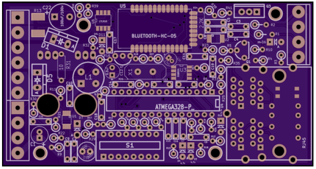
This morning I placed orders for the remaining parts and the PCB for the standalone version of the Arduino based Alternator Regulator.  Here is a 'projected' picture of what the PCB will look like:


And the schematic can be found in the Schematic Link above.  BOM/shipping cost came in at $83 for the regulator and just under $100 for everything:  Regulator, Temp probes, Current Shunts, etc.  All but connection wire and fuses.

The basic concept for this regulator is the same as the integrated Engine Controller and Regulator, with a few differences:
  • Found a simplified FET boost-driver (LT1910) that has a built in Booth PS.  It should allow N-Channel FETs to be used from 12v to 48v on P or N type alternators w/o any hardware changes.  Will be interested to see how it works!
  • Have eliminated the hardware remote LCD panel, the unit will just start when power is applied and optionally communicate status via Bluetooth. (Or the built in Serial port)
  • Have on board DIP switch and LED for stand-alone configuration and operation.  Just select the battery type, size, and some other special features and connect it up.  Nothing else is needed to get it to work in its basic function.
  • Sync port to coordinate functions between two regulators charging the same battery, ala in a twin engine boat.  Mostly this is to share Amps produced, but as the firmware progresses, might find other needs for this coordination.

    It still retains the ability to monitor and manage Amps (Watts) as well as Volts.  This can be used to better decide when to change charging states (terminating the Acceptance phase based on battery need vs. pre-determined fixed amount of time), as well as doing functions to protect the Alternator, or limit the load on the engine.  I plan to have a few 'pre defined' scenarios built in and selectable via the DIP switches, and hope to have a simple user interface available via the Bluetooth (and/or Serial port) to monitor status as well as allow for additional  custom configuration of different scenarios to be saved in the Atmel EEPROM.  Of course, one could always modify the firmware and get any scenario they wanted!

    I should be picking up the parts late June, early July.  Then will be building them up.  Till then, I continue to use my Fixed voltage truck regulator on the main house battery alternator, and the integrated Arduino controller on the Generator.


    Thursday, May 23, 2013

    Posted draft Stand Alone Alternator Regulator Schematics

    This morning I placed the draft schematics for the stand-alone (alternator only) version of this project to the Schematics tab above (click on the Stand Alone Regulator' folder.

    This regulator will be based on the controller project and share a lot of the code, but will not include any of the Engine control functions.  Key features of this stand-alone regulator are:


    • Active management of Alternator for both Volts and Amps (Watts)
    • Ability to use Amps as a way to judge when a battery is fully charged, as opposed to pre-defined time value (this is the key feature)
    • Paralleling ability for coordination between two regulators in a twin-engine setup (ala, marine use)
    • DIP switches to be used to select a series of pre-configured charging profiles.
    • Fully support of P or N type alternators from 12v to 48v

    It also includes a Bluetooth module, for future communication to computers, phones, etc. for status updates as well as finer control of the configuration.

    As always, it is fully programmable via a Service connector, and posted in the Public Domain.

    One major change I am excited about is the Field driver - I located a self-powered Boost driver (LT1910) that looks like it will allow for a fully configurable P or N type alternator support from 12v to 48v without any hardware changes.  Will be going to FAB in a few weeks, if anyone is interested in this let me know.


    Sunday, June 20, 2010

    PCB Errata

    Design release V0.1.4

     A problem with low voltage cutout has been IDed in the FET driver chip.  More details here:
    http://arduinoalternatorregulator.blogspot.ca/2016/04/regulator-stops-working-when-enable.html


    (Click for larger view)


    Design release V0.1.3


    (Click for larger view)

    Some photos showing corrections:

    R6 / R33 moved to bottom of PCB correcting Tx/Rx 

    Ordering

    To assemble an Arduino Alternator Regulator, you will need to order the following components:
    • PCB
    • Electronic Parts
    • Heat Sink
    • USB --> TTL adapter board (optional)
    • USB Male – Female extension cable for above
    • ICSP programmer w/6-pin adapter
    • 4x TO-220 Insulated mounting hardware
    • Thermal grease
    • Mounting hardware
      • 4x  #6 x 3/4" pan-head machine screw
      • 4x #6  x 1/4” insulating nylon standoffs

    Total cost for all of the above should be will under $100,  and much lower depending on if you implement Bluetooth or not.


    PCB

    I often have a supply of PCBs available, see the right to check that status.  Alternatively you can use the resource tabs above and download the latest GBR files to be used with the PCB fabricator of your choice. (or the CAD files, make mods as you wish and go from there!) When making up the PCBs I use standard thickness and 1oz copper, you can consider upgrading to 2oz copper if you expect to drive high field current (or perhaps two alternators in parallel).  Alternatively, there are open places in the solder mask which can be used to 'reinforce' the field drive traces - just solder on some short wires in those spots to help carry any field current.


    ELECTRONIC PARTS

    For convenience I use Mouser.com for sourcing my parts - to be honest, mostly because they seem to not mind too much (or at least do not complain too much) selling small quantities of parts, and their web page is a bit better then other supply houses when it comes to locating and comparing components.  Under the resource tab 'Parts List' above you will find a .xls sheet with the BOM, I also have places a 'scrubbed BOM' at Mouser.com (as of December 2014) that can be access using this link:
          https://www.mouser.com/ProjectManager/ProjectDetail.aspx?AccessID=f0133335ad


    Do note this mouser BOM is for v0.1.4 of the PCB and includes the Bluetooth module.   If you wish to not use the Bluetooth, make sure to check the schematic for part changes - specifically:
    • Do not order the RN-41 Bluetooth module
    • Replace D18 with a 10K resistor
    • Change C19 to a 0.1uF capacitor
     You might also be able to order some of the other needed components from Mouser as well, like a usable heat-sink, the TO-220 mounting hardware, etc.    But then, you might also be able to come up with lower cost sources...

    And of course there are other sources than Mouser.com  - nothing magic about anything in the board - do take note the 8Mhz crystal  picked uses 33pf loading caps (it was what was available when I 1st selected parts for this project), if you select a different crystal - make sure to match up the loading caps C13 / C14  to the specs of the crystal.


    HEAT SINK

    Perhaps the hardest part to source.  The Arduino Alternator Regulator really does not produce that much heat, but a small amount of thermal capability is needed - mostly on Q1 and U1.  When designing this I selected a heat sink largely for its physical protection.   The part I designed to is a: Hongfa HF92B-120 (http://octopart.com/hf92b-120-hongfa-19677676).   It is designed to support a couple of SSRs (Solid State Relays) and was selected due to its large flat space in the middle.  In fact, the PCB is designed to fit this space with an overall size of  105mm x 55mm.  The problem is this part is a PITA to source - and my experience with the one supplier out of Australia is a little less then positive - esp with regards to shipping costs.  So, here is some additional data for you and some ideas for alternatives:

    Heat Displacement of the regulator is documented here:
         http://arduinoalternatorregulator.blogspot.com/2014/04/confirming-power-dissipation.html

    In most cases, it will be rather modest.  Some ideas for alternatives heat sinks might include:
    • Modify more commonly available heat-sink, removing a fin to get a bit more width if needed.
      • For example:  Orman - Y92B-A150N
      • Wakefield  423K
      • Any Fine Type heat-sink..   Look on Ebay, local supply house, scrap bin
    • Utilize some extruded 'L' shape aluminum stock?
    • A die-cast metal box?
    The heat needs of the regulator are rather modest and likely easily solved.  More one want to think about physical protection  (but don't try an all-plastic case, there is some heat carrying needs!)


    COMPUTER ADAPTERS

    There is one adapter you will need, and one more you likely will want.  Because a custom boot-loader is needed (a 3.3v opti-boot), you will need to gain access to an ICSP tool.   And ideally a 3.3v capable one.  I use a widely available open-source tool based on the USBasp.  It should be available off of EBay for under $5 or so, make sure you have some way to get to the 6-pin ICSP connector used by the Arduino Alternator Regulator (Either via an adapter board, or just some jumper wires as I use).  There are a few more details involved which I have documented here:
    http://arduinoalternatorregulator.blogspot.com/2014/06/burning-arduino-33v-8mhz-atmega328p.html

    Make sure to note the need to have a good solid 3.3v power source while burning the bootloader - (a USBasp by its self will not be sufficient)  Either hook up the regulator's Enable pin to an external power supply, or you can get sufficient current if you also use the Serial Service Port adapter described next.

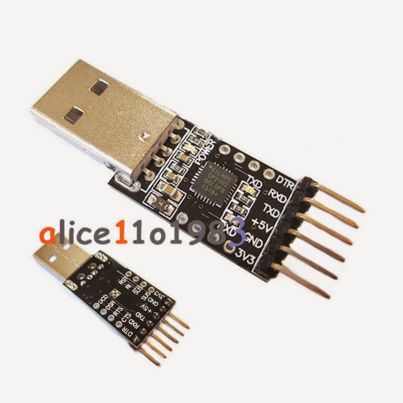
    The other board which you might find helpful is a USB <--> Serial adapter board.  Once the Bootloader is flashed in you can use this board via the Service Port to load sketches.  It also provided a way to gain access to Serial ASCII string status outputs as well as a way to send ASCII commands to the regulate - if you do not wish to use the Bluetooth module (or wish to 'override' it temperately).  I have designed the regulator to directly connect with certain 6-pin adapters - and I selected those adapters as they are able to supply 3.3v as well as 5v without any switches or jumpers needed.  In this way, all my projects use the same adapter board and you do not need to worry about setting switches.  Take note this is NOT the same pin-outs as used on the small Arduino boards...

    I purchase mine from Ebay for around $2 each using the search string: “CP2102 USB 2.0 to TTL UART Module 6Pin Serial Converter STC Replace FT232” .  If you take care to get one with the pinout of this spec you can directly plug it into the Service Port:
        1. DTR
        2. RXD
        3. TXD
        4. +5V
        5. GND
        6. 3V3

    Example of 6-pin adapter with correct pin-outs
    (Click on picture for larger view)


    Of course other serial adapters can be used (you can even pull the ATmega328 out of an Arduino UNO and use that) - you will just need to match up the pins. You do need to make sure you can get access to the DTR signal, as that is used by the Arduino IDE to reset the uC and allow sketches to be loaded.  Do not confuse this with adapters which have a pin labeled 'reset' or 'rst' - often those pins are used to reset the USB adapter, and will not work with the Arduino IDE without modification.


    MOUNTING HARDWARE

    Finally you will need some mounting hardware.   TO-220 insulating hardware and screw sets.  Mouser has them (e.g.: 534-4724 for a couple buck each), or you can order in bulk - myself I again look to Ebay!   Make sure to get some thermal grease as well.

    To mount the regulator to the case / heatsink of your choosing you can use nylon standoff spacers that match the off-set you used when soldering in Q1, Q2 and Q4 (the TO-220 parts mounted on the bottom of the PCB).  Used 1/4" - because in the USA 1/4" nylon spacers are easily found.  But of course you can use what you wish.  The 4 mounting holes in the corners of the PCB are 0.120" in diameter (approx 3mm).  I found they are just right to allow taping for a #6 machine screw - a 3.5mm machine screw should work just as well.  I then just ran a machine screw up through the underside of the heatsink, put on a spacer and gently screwed it into the PCB - letting the PCB act as the 'nut'.  If you want you can add threaded nylon spacers to the top of the PCB, screwing onto the protruding stud and perhaps that can hold some type of overall cover.    To see a bit more details on how I mounted my regulator, click here:
    http://arduinoalternatorregulator.blogspot.com/2010/06/assembly-and-programming.html


    Installation


    See complete documentation "Arduino Alternator Regulator Guide"  under the Reference tab above.


    Capture Run Data

    After you have things installed and running, consider capture debug data for your own use as well as sending it to me to help improve the core code.  See: http://arduinoalternatorregulator.blogspot.com/2014/08/capturing-log-data-for-assessment.html  for details on how to do this.