Showing posts with label Design Choices. Show all posts

Wednesday, August 1, 2018

Screen Shots of a 'System' install

I have been using the soon-to-be-available simple 2" dash display, and today took some snap shots.  On Viking Star the VSR Alternator Regulator connected locally to the alternator and working in conjunction with an RBM (Remote Battery Monitor) .  From the VSR Alternator Reference Guide, here is how things are wired up:


With this setup the Alternator Regulator is wired locally at the alternator; monitoring its voltage, current, and temperature.  The Battery Monitor is back at the battery monitoring its voltage, current, and temperature.  A single CAT-5 cable is ran from the engine room back to the battery.  To connect the simple Dash-Display all I needed to do was continue this CAT-5 cabling from the VSR Alternator Regulator up to the dish display.  While running I took these photos:


Shown here are two screens, one for the Battery and one for the Alternator.  (Note, all these screens were automatically created by the simple Dash Display, no setup needed - just plug in the CAT5 cable).  Some details I wanted to point out:
  • A key value of the RBM (Sensor Extender if you will) is that it simplified wiring.  Only a single CAT5 needs to be routed back from the Engine room.  The VSR Alternator Regulator is provided true Battery information in this way.
  • This leaves the Alternator sensing wires to sense the Alternator, voltage and current.
  • And to install the simple Dash Display, only a CAT-5 cable was needed.  No need to run ANOTHER set of sensing wires to the battery and alternator.

While running I also want to point out some details shown on the screen-shots above:
  1. Note how the Battery Voltage is 14.4v (its target) while the Alternator voltage is a bit higher at 14.5v.  This is because of voltage drop of high current over the battery cables.
  2. Note also how the battery amps are higher then the alternator output.  This is because I also have solar panels installed which are not (presently) participating in the systems communications network.
Fun and interesting if you like to watch things like this -- but one thought related to point #1 above:  If while monitoring you see the voltage difference between the battery and the alternator starts increasing, this is an indication of a wiring failure in the high current wires.   Being able to monitor and catch this is one safety ability a Systems Approach allows.


Thursday, March 8, 2018

An App!

When the VSR Alternator Regulator was 1st created it was envisioned that much of the users interaction -- configuring, monitoring, diag -- would be handled via an application running on your phone / tablet / PC.  The resulting ASCII status and command strings were intended to provide platform independent communications to that app -- more so, that ASCII communications was never intended for humans to futz with. 

But the app never got developed, and it was kind of lucky that the ASCII strings were human readable.  This background may help explain why they are not all that user friendly.


Skipping forward, Rick Bell has been working on an Applications and posted his works at Back Stage Sailing.  Here is a link to the application in its Beta form:

https://backstagesailing.com/downloads/category/osenergy-configuration-tool-beta-versions/

And a users forum:   https://backstagesailing.com/user_forum/

 I am so happy to see an app being worked on, as it opens up so many possibilities to simplify advanced installations, from single users to professional installers.   Few folks will master the ASCII command set, but with a good app they will not need to!

Have a look, download the Beta and give Rick some feedback.  And keep your eye out, there is more to come in this area of communications over the coming year...


Thursday, January 11, 2018

Why all the code pushed up to GitHub?

Some folks may have noted a LOT of code pushed up to Github over the past few days. 

I am refreshing the DC Generator controller design, including bringing it up to a like level of OSEnergy support as the Alternator Regulator.
http://smartdcgenerator.blogspot.com/

As I do the software porting / refresh there will be changes to the Alternator Regulator source code which is not directly related to the Alternator Regulator, but are being made to allow common source code / code reuse with the DC Generator controller.  Mostly it is naming, and use of #defines and include files.

Some of the edits include changes in the support libs RV-C, so make sure to bring down and update both the source and the libs directory on your local machine.


Sunday, July 27, 2014

Thinking about Float - A new approch??

The purpose of Float mode is really two:
  1. Provide makeup energy to compensate the battery for any self discharge
  2. Cover house power demands using the Alternator.
In reality, makeup energy is more of a shore-power topic, while an underway Alternator Regulator would do just fine focusing only on covering house loads.  The traditional approach for managing these two goals is to select a voltage just slightly above the At-rest voltage of the battery and holding it here.  Making adjustments for battery temperature along the way.

But it occurred to me this approach really is back in the world of voltage-only centric thinking, and is in fact an indirect way to achieve the real goal.  After all, what we REALLY want to do is provide some energy to the battery for point #1, and make sure current flow out of the battery is as close to 0A as possible for point #2.

Rather then try to develop a precise voltage to hold in achieving these goals, why not just manage to the goals them self??  Perhaps rather then holding a FLA battery at 13.4v, we instead manage to 1% of its Ah capacity (ala, 1A flowing into the battery).  And for batteries where we don't want to give any self discharge makeup energy, we hold battery amps to 0A.

When I return to the boat I may look at these ideas;  to me it makes more sense to manage towards to real goal then try to walk a thin indirect line hoping we got it right type of goal..


A closer look at LiFePO4 battery needs

 There has been some changes, follow this link for the latest:

http://arduinoalternatorregulator.blogspot.com/2014/09/a-final-approach-for-charging-lifepo4.html

===============================================


Someone is building up a regulator (and integrated engine / DC generator controller) for use with LiFePO4 batteries and an associated BMS.  This has given me the change to share Emails with folks knowledgeable about these quickly establishing technologies.  It has also given me an opportunity to think a bit about how to adjust the Arduino Alternator Regulator to better support their needs.  With the next release of source (will be v0.1.3) the following changes / additions will be included:
  • Revised default CPE #8, better optomized for LiFePO4 batteries
  • New CEP entry 'Min Charge Temp', to mirror existing 'Max Charge Temp'
  • New Feature-in mode --> Force to Float.

The CPE has just a few changes, mostly fine tuning voltages.  In support of these changes I have found a few more manufactures datasheets (See Resource link above).  Anyone has additional info / insight please send it on! Charge profiles for LiFePO4 batteries share a lot in common, but there seems to be some slight variances with some manufactures - perhaps to 'gain a leg up', and perhaps also to lessen lifespan.  The values I have placed in the default are a bit on the conservative side in that if there was an opportunity to 'push the battery a little' - I did not take it.   Case in point the target voltages and the 30 minute cap on Acceptance phase.  Some manufactures have a higher target then I am using, to pack more in - and there is some indication that LiFePO4 batteries really like to leave the table a little hungry.  Meaning, charge them to 95% and stopping makes them happiest (unlike Lead-acid cells that really like to get a full 100% charge for longest life).  Here is what I now have for default (remember, this is for a normalized 12v/100A battery, and will be scaled depending on the DIP switches):
  • Volts target:           14.6v  (3.65vpc)
  • Amp Cap:             50% of Ah capacity (50A)
  • Absorption exit:       3% of Ah capacity (  3A)
  • Float Voltage:        13.6v   (3.40vpc)
  • Revert to Ramp:    13.3v   (3.325vpc)
There also a new low cut-off temperature of 0c (32f), and a more restrictive high limit of  45c (113f).  Some batteries indicate they can be charged at outside these ranges; you will have to set that using the ASCII commands and/or recompile the firmware.

As this is a change in the CPE structures any previously saved ASCII changes in the CPUs flash will be overwritten when you upgrade the firmware..  And the associated ASCII commands have also been changed.


The final addition is a new use for the Feature-in port -> Force to Float.  This will force the regulator to stop charging and go into Float mode (or post-float if you have configured things to bypass float).  It can be used  with an external BMS that has perhaps detected an out of balance / single cell within a battery bank which is full.  It lets the BMS stop the charging to protect that cell and/or the BMS system.

Force-to-float  is only enabled when CPE #8 is selected and is active at all times - including boot-up (e.g., starting the engine when the BMS is indicated 'Do Not Charge' will cause the regulator to immediately go into Float mode.)  As such Feature-in will no longer be able to restore the regulator to default or select Equalize mode.   If you need to do one of those, change the DIP switches to something other then #8 and reset the regulator,  or use the ASCII restore command.


Wednesday, July 16, 2014

Feature-out option: Battery Combiner

It seems a battery combiner are somewhat common when more then one battery is in a boat.  I thought "Hey, why not add some code to let the Arduino Alternator Regulator controlling an external relay and act as a battery combiner".  But I had never really sat down and thought things through - till now.

While reading material found on the web - both from commercial suppliers (aka, people who make combiners), and forums I found a mixed bag.  Talk about sharing current, self adjusting due to internal impedance and its change vs. SOC (State of Charge), Gassing, etc.   The EE in my followed much of the reasoning (where it was provided), but also started to call B.S. on other parts of it.  After all, who knew:
  • ". None of the batteries will ever be 'overcharged' as a result because the charging voltage is controlled."
  • "..the reason for the extra wire length [between a combiner and the batteries] is to act like an electic <sic> spring which allows the [product name] to produce a higher current"
Both of these statements are flat wrong.  Holding a battery at its gassing voltage well pasts the point where its acceptance current indicates a fully charged battery will do nothing but create heat and risk boiling off the battery.  And I for one never know the resistance of a wire could act like an 'electic' <sic> spring!  (But then, 6' of 6g wire does have a little over 2.5uH of inductance - in free air.  And there is always some level of AC superimposed on top of the DC voltage.  So, there is likely some inductive reaction that can be seen.)   

Now combiners are not necessarily bad, but one needs to really think things through before blindly putting one in.  Read the manual, be very careful about max wire size as well as min lengths, and consider combiners which provide a high-voltage cut-off, preventing overcharging (or sorry, preventing excessive heat and boiling of electrolytic from the battery).  Properly installed a combiner can serve a valuable function and not cause damage.


 Here is my take on things to consider with combiners.  First off, I think there are two broad deployments cases.

       Case 1:  Two independent batteries, each with their own charging source.
       Case 2:  Two independent batteries, only one of which has a charging source.

The 1st case is what I have on Viking Star, a starter battery connected to the factory (unmodified) engine alternator, and the house battery with its own large alternator.  Here the starter batter is recharged very quickly after engine starting and it would be nice to shunt some of the unused factory alternators capacity over to the house battery to help during the Bulk phase of its charging.  Case 2 is perhaps an example were a bow-thruster battery has been installed that needs to be recharged, or a small installation where there is only one alternator, connected to the house battery, and we need to use the same alternator to recharge both batteries.  Without risking boiling off the starter/thruster battery.  Here is what I have added to the Arduino Alternator Regulator source to address each of these conditions.


 Case  #1:  Using 2nd battery/alternator to ‘help’ the house battery during Bulk.
In this example there are two fully independent battery and associated charging systems.  And example might be the factory alternator + starter battery, and a house battery with its own alternator using the Arduino Alternator Regulator.  The starter battery will likely be quickly recharged after the engine starts, leaving a significant amount of unused capacity in the starter battery’s alternator. 


Receiving Help combiner profile (default)
The figure above illustrates when we want to combine the two systems (between points ‘X’ and ‘Y’).  Specifically during Bulk we want to:

  • Wait until the house battery reaches 13.2v before enabling the combiner.  If we combined sooner there is a risk of pulling energy from the 2nd battery, as opposed to only asking the 2nd alternator to share its capacity.   13.2v will also reduce the voltage difference between the two batteries thereby minimizing initial surge current. 
  • Break the connection of the two batteries after 14.2v.  With the assumption the 2nd battery has its own charging source that will handle all the recharging needs of that battery, we do not want to ‘override’ those decision.   14.2v was selected under the assumption that many ‘starter’ batteries are connected to a default internally regulator fixed voltage alternator; those are often in the 13.8 to 14.2v range.


Case #2:  Recharging a  2nd battery which has no charging source of its own.
In this example there are still two independent battery, but only one charging source.  A representative example would be a house battery / alternator being controlled by the Arduino Alternator Regulator, and a 2nd battery used  perhaps to power a bow-thruster, or even a starter where there is no 2nd alternator.  Unlike the situation above were we are looking to gain assistance from the other battery/alternator, in this case we are asked to be the charging source for the 2nd battery.

Charging 2nd battery combiner profile
Here the 2nd battery parallels the charge profile of the main battery, and because we are not actively managing the 2nd battery we cut off the Acceptance phase after a relatively short time ( Points ‘C’ to ‘Y’ above) to reduce the risk of overcharging  the 2nd battery, in effect boiling  it off.  


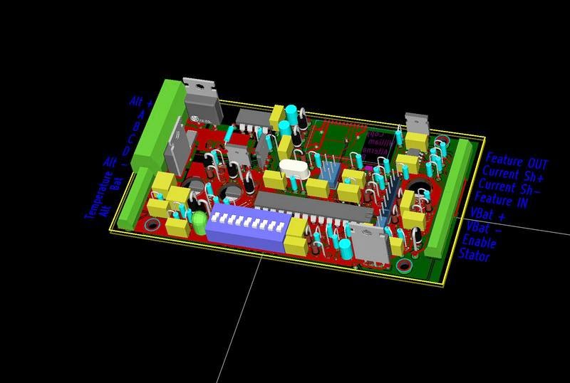
All these parameters are adjustable in the source code, voltages, times, etc.  Select the Feature-out combiner option, add a large capacity relay (being careful not to overload the feature-out current limit of 500mA).  Make sure there is sufficient smaller-gauge wire (ala, 10' of 10g wire) to manage peak currents and you can have a reasonable 'combiner'  But in each case remember:  

Care must be taken in each of these situations to protect the 2nd battery and charging system; remember the Arduino Alternator Regulator will focus on its battery and adjust things to its needs with NO regard to the other batteries needs 


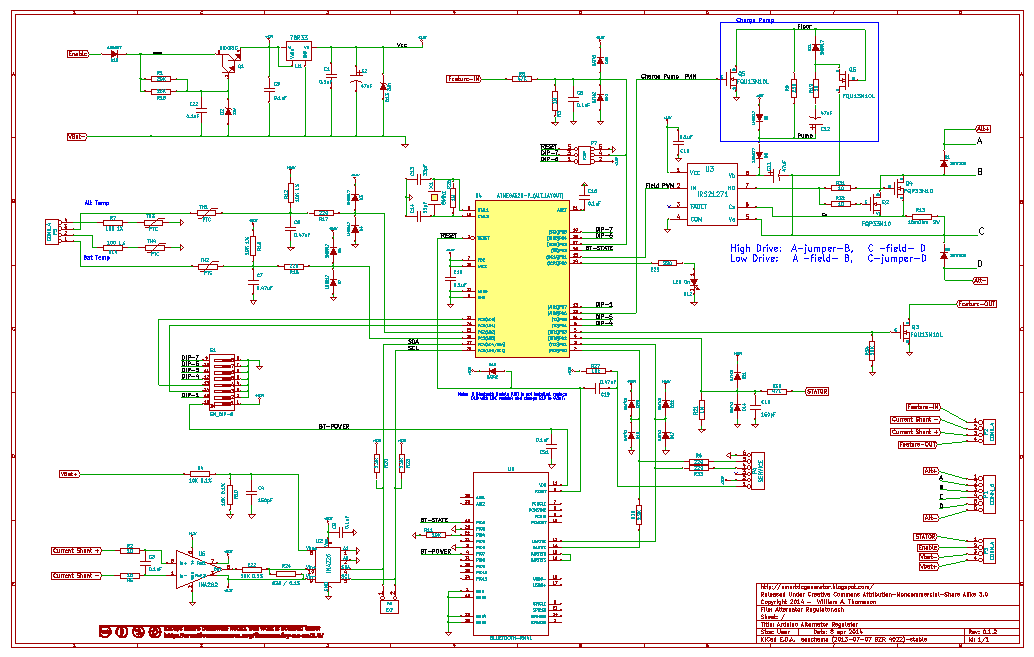
 These capabilities will be in the next posting of the source, v0.1.3 and above.


Thursday, July 10, 2014

A choice: Crystal vs. Ceramic Resonator for the Atmel/Arduino?

I have been reviewing the design of the Arduino Alternator Regulator, looking for ways to make
Which to use?
improvements, as well as moving it towards full SMT components (or at least as many SMT as practical).  One area that I have been poking at is the source for the Atmega328 CPUs clock.  Of course there is the internal 8Mhz RC oscillator, and that might actually work - given there are not really tight timing requirements (outside of the serial port); but for now am still leaning towards an external clock of some sort.  The two primary candidates being: Crystals vs. Ceramic Resonators.

The ATmega will work just fine with either, and both require little external components.  In reading up on them, here is what I have summarized:
  • Crystals are MUCH more accurate, like 100x more so.  (0.0005% vs 0.5%)
  • Resonators are little less costly.  (Often see them used in mass volume applications)
  • Resonators typically have biasing capacitors built in, further reducing costs.
  • Crystals are more fragile, subject to vibration.
  • Resonators are better able to withstand ESD
  • Resonators are often (but not always) physically smaller

Perhaps the largest number of conversation seems to focus around costs.   At least in very high volume deployments.  A ceramic resonator is a little less costly then a crystal and when combined with them often including the bias capacitors in the same package this gives further savings.  Availabity  in smaller packages can give further savings via PCB space.

But resonators are oh so more less accurate then crystals.  And with regards to costs:  looking at Mouser.com, there really is very little cost delta between them and resonators in the small volumes I am playing with.  Pennies.

One thing stood out to me though, and it was kind of buried when searching the web:  Resonators are physically more tough.  In fact, searching for 'crystal automotive' and you will find a few new 'hybrid' devices out there just being brought to market - in an attempt to get the higher accuracy of crystals for more demanding automotive applications.  Currently in cars: resonators are king.

Plus, the Arudino Uno uses a resonator - so I guess it is OK for accuracy. . . .

Bottom line:  I will be revising the design to use a Ceramic Resonator in the next revision.  Both for this as well as for the integrated controller.  And it was the toughness that swayed me.  And fwiw, am also going to use the through-hole 'tear-drop' style (as pictured above).  Reviewing the datasheets for the small SMT resonators reveled they are not sealed, and as such can not be conformal coated...


================================================================


BTW:  Another question I did some research on was the at times appearance of a 1M resister between XTL1 and XTL2 on the ATmega CPUs.  Most puzzling was I could find no reference to such in the Atmel datasheet, and yet the Arduino UNO has one installed.

Bottom line:  a feedback resister is needed to 'kick-start' things (Negative feedback), and it does not matter if a crystial or resonator is used - one is needed.  However the ATmega CPUs already has one built in.  Adding an extra 1M external does not help anything, and in fact can reduce operating noise margin..

More details in this app note:
www.atmel.com/images/atmel-2521-avr-hardware-design-considerations_application-note_avr042.pdf


Tuesday, April 15, 2014

Burning up Alternators at Idle....

One thing that has always bothered me was when the engine idles down to a lower RPM and the Alternator is still trying to pump out a massive amount of power - regulator will end up driving the field to Full Power 100% field current trying to keep up. The question is: Are Alternators able to handle this? In some ways it is kind of like lugging an engine uphill in high gear..

I know this is not an Alternator Rotor
But you get the idea..

This last week I had someone contact me.  They have been poring over both this Arduino regulator project, as well as its companion http://smartdcgenerator.blogspot.com and asked the question: "Am I doing anything to reduce Field current at low RPMs". He went on to share an experience of a boat using large frame Leece Neville 4900 series alternators (the same 35lb units I use for our main engine house alternator) driving massive loads  to power engine room blowers via inverters. After an extended period of time at idle (and likely in a very hot engine room - these were MTUs in a $$$ go-fast craft), there was a failure in the field - total melt down of the Field / rotor..


My initial intention of adding the 'Small Alt' mode selectable via the DIP switch was to protect smaller framed alternators from prolonged periods of high current output. Ala, that 200A Hot-Rodded alternator in a standard small frame.. Small Alternator mode will cap an alternators output to 75% of its capability (configurable of course), at all charge points. But it seems perhaps more might be needed - especially given the real life experience of someone melting down my beloved Leece Neville large frame alternators just idling around...

So, I have added a new feature to further restrict how hard the field is driven when the engine is at idle.  By sensing this RPMs vis the Stator wire, I can tell when we are near idle - or at least near the lowest RPMs that the engine has been operated at..  And when at idle I now cap the field to 50% of its max drive.  This % is increased up to the max allowed (100% or 75% depending on the DIP switch, and if the defaults have been adjusted).  And there is a new parameter in the $SCA: command to configure this capability.


Blue line shows default idle capping curve.
Red and green give an idea of some other configurable options via the $SCA: command..
Of course you can also use the $SCA: command to also disable this feature. Right now I have the '50%' hard codded in the firmware; starting to get a bit too many configurable parameters. If someone has any feeling for the right % value to use at idle, let me know.  If you want to change it in the firmware look at the  "set_VAWL(float passedV)"  helper function in "calculate_ALT_targets()" 


I hope this will help out some installs.  Though we never had any issue pulling max amps (and max field) for several hours  at a time while idleing around during Christmas Ships with our LN 4900 270A alternator, clearly someone has..   Perhaps I can feel even better now - protecting the Alternator just a bit more...


Thursday, April 10, 2014

Confirming Power Dissipation

As I go through to finalize the next rev of the PCB I though I would revisit my heat calculations.  There are two (three really) sources of heat in the regulator:
  • Darlington pre-voltage regulator (Q1)
  • Final Voltage Regulator (U1)
  • Field FETs (Q2 / Q4)

I calculated the Power Dissipated in Watts for each of these, and here are the results:


For the power supplies I assumed a current draw of 165mA, this is approximately  two times the expected maximum internal current draw. 


FET power dissipated is dominated by static losses (simple "P = I^2 * R" calculations).  The Ron of the FETs I adjusted for a 100c junction temperature.  And it should be noted, this is per-FET (remember, there are two of them).  Switching losses (dynamic Pd) is so small; primary because our PWM frequency is very low at 144hz - the max switching loss I calculated was 3.4mW, so we can in effect ignore switching losses.


At first glance the worst case appears to be 2.75W + 2.75W + 12W + 1.3W =  18.8 watts.  The heat-sink I selected for this design (Hongfa HF92B-120) has a Thermal Resistance of 1.1C/w.   At 18.8w we would expect the heat sink to gain 18.8*1.1 = 21c.  Put this into our 120f engine room we get to a nice warm 160f heat sink.


In reality  it is unlikely we will see both the system voltage AND the field current at max at the same time.  After all, if indeed we were running at 80V and drawing 30A of field current, this would be 2.4Kw of power JUST TO DRIVE THE FIELD!!   More likely is as system voltage increases we would see lower Amps drawn by the field. 


Lets take a look at a couple more realistic extreme examples, a single Alternator in a 12v:
  • 12v system
  • Single large frame alternator drawing 10A field  (This is about 2x what a common alternator will draw)
  • 100mA system draw (you will have to trust me on the new Power Supply figures I use below)
 Now total power becomes: 0.3W + 0.3W + 0.4W + 0.75W = 1.9W, or a 2c temperature rise. Now in our 120f engine room we are running at only 124f.  Will not even notice it.


Or, look at a this:
  • 48v system
  • Single large frame alternator drawing 3A field (a special 48v alternator - Higher volts means lower Amps)
  • 100mA system draw.
Comes to: 0.03W + 0.03W + 4.3W + 0.75W =  5.1W  comes out to perhaps 130f.


What about a realistic 'heavy' system?
  • 24v system 
  • 2x large frame alternators in parallel - 20A field current.
  • 100mA system draw.
     1.2W + 1.2W +  1.75W + 0.75W = 4.9W   --> gets us again  up to 130f in a 120f room.

What is the secret?  Looking at the power equation:  P = I^2  * R, to lower Power we can lower I or R.  The 1st was done by using two FETs.  Cut the field current in half between the two (FETs are largely self-balancing when ran in parallel).  We get a ton of bang from this due to the squaring of current in the power equation.   Next I selected a FET with low Ron.  With the low PWM frequency we can trade off higher gate capacantance to get a low Ron and not have to spend $7 per FET.

So, there it is.  Large Field currents, high system voltages, and looks like the Arduino Alternator Regulator will keep its cool.


Tuesday, April 8, 2014

Working through non-preferred charge management schemas

The core approach for this regulator is that we stay in Acceptance Phase until the battery is full.  And we decide the battery is full my measuring its acceptance amps.  When the battery is full, it says 'Enough' and we move onto float.

But what if the user has some reason to not want to do that?  What if they don;t want to hook up the Amp shunt, or perhaps want to use the Amp Shunt only for a different reason - and they WANT to use only time-based criteria for deciding when to leave Acceptance more. 

It is What If';s such as this I have been working through, to see how the regulator will react.  If the user had configured the regulator to use only time to exit Accept mode (by setting 'Exit_acpt_amps' in the CPE  = 0), then only time would be used.  The 'Exit_acpt_time' duration.  Tonight I added a 2nd option.  Setting the Exit_acpt_amps = -1 will now cause the regulator to move from Acceptance phase either by exceeding Exit_acpt_time duration, -or- by exceeding 5x the amount of time we were in Bulk.  This way of the battery is basically charged when we start up the regulator we will be in Bulk for a very short time, and now we will be in Acceptance for a like very short time.

The 5x is set in the code by
    #define ADPT_ACPT_TIME_FACTOR    5


This new Adaptive Acceptance Time Mode will also be triggered if the regulator is unable to measure amps via its shunt - either because something broke, or because the user did not wire it up.  In either case, by having an adaptive time frame the battery gets a bit more protection when we are unable to actually measures its appetite.

Over the next week or so I intend to work through other such 'non-preferred' scenarios and will be modifying the code accordingly.


Monday, April 7, 2014

Posted release v0.1.2

Tonight I posted the files (Schematic, PCB GBR files, BOM) in the respective resource tabs above.  This version has had several changes from V0.1.1 - mainly:
  • Changed FET Charge Pump from soft-floor to hard-floor design.
  • Scrubbed reset ckt - RN-41 has built-in pull up, this messed with time-constants of C19
  • Scrubbed all the protection diodes, removed Zeners.
  • Added PTC fusing for the NTC temp probes, to better survive accidental shorting to battery.
  • Change Amp Shunt pre-scaling chip to INA-282.  This will not support BOTH high or low shunts, and it will also allow measurement of + or - amps.

Here is the current schematic in picture form, a readable .pdf is under the Schematic tab above:


And here is a 3D CAD drawing of the board:


This design is being sent off the http://smart-prototyping.com to see what quote they will come back with in regards to the PCB and assembly.  I am looking forward to not having to hand-solder the small parts and hope they come back with a reasonable amount.   If you are interested, send me a note.  We have about 6 boards 'in the queue' now, and I think they can do more w/o any issues :-)